
| Start of section
Production, amateur Radio amateurs Aircraft model, rocket-model Useful, entertaining |
Stealth Master
Electronics Physics Technologies Inventions |
Secrets of the cosmos
Secrets of the Earth Secrets of the Ocean Tricks Map of section |
  |
| Use of the site materials is allowed subject to the link (for websites - hyperlinks) | |||
Navigation: => |
Home / Patent catalog / Catalog section / Back / |
|
INVENTION
Patent of the Russian Federation RU2202048
![]()
WINDOW WINDSCREEN AND PULLEY OF WINDOW WINDSCREEN
The name of the inventor: Mozgovoy Alexander Ivanovich
The name of the patent holder: Mozgovoy Alexander Ivanovich
Address for correspondence: 347900, Rostov Region, Taganrog, ul. Lenin, 96, TsGPB them. A.P. Chekhov, the patent department
The effective date of the patent: 1998.02.17
The invention relates to the field of wind power, namely wind turbines with a rotor axis perpendicular to the direction of the wind. The technical result, which consists in increasing the power of the wind wheel, increasing the blade area and reducing pulsations, increasing reliability, simplifying the design, and reducing the metal capacity, is provided by the fact that in the carousel wind wheel containing the frame flaps installed on the vertical axis, the pivots articulated In sweeps, rotatably and cyclically interacting with the stops and swing stops of the blade fixed to the sweeps according to the invention, the blades are flat and the axis of rotation of each blade divides it into unequal parts with an area ratio ranging from 10: 1 to 3: 1. When In the rotor blade of a carousel containing a rectangular sheet fastened to the axis according to the invention, the axis is fixed to the sheet with a distance from the edge by 1/10 ... 1/3 of the length of the blade.
DESCRIPTION OF THE INVENTION
The invention relates to the field of wind power, namely wind turbines with a rotor axis perpendicular to the direction of the wind.
Known wind turbine, which has impellers lower and upper tiers, including fixed on the vertical shaft holders with stops and placed between the blade holders, each of which is made up of a composite of aerodynamic profiles. The wheels rotate in different directions, performing the functions of a control oscillator (see SU, 1622609 A1, class F 03 D 9/00, 23.01.1991).
This wind turbine has a low efficiency, because The power of the wind flow is transmitted through the blades only from one side of the axis of rotation.
A carousel wind wheel is known, which contains frame flaps installed on the vertical axis, paddles hingedly fixed in the swing with a pivoting ability and cyclically interacting with the stops and pivot stoppers fixed to the mahas, while the rotor blade of the carousel contains a rectangular sheet fastened to the axle (see Fig. SU, 1772407 A1, cl. F 03 D 3/00, 30.10.1992), on a set of essential features taken for the closest analogue of the invention (prototype).
This wind wheel has a low reliability and does not provide a reduction in the pulsations of the torque.
The technical result, which consists in increasing the power of the wind wheel, increasing the blade area and reducing pulsations, increasing reliability, simplifying the construction, and reducing the metal capacity, is provided by the fact that in the carousel containing the frame flaps installed on the vertical axis, the pivots articulated In sweeps, rotatably and cyclically interacting with the stops and blade rotation stops fixed on the sweeps according to the invention, the axis of rotation of each blade divides it into unequal parts with a ratio of areas in the range of 10: 1 to 3: 1, and the blades are flat, Each vane contains rigidly connected horizontal rods and vertical stiffeners, the blades can be pivotally pivotally mounted in panels rigidly fixed in the sweeps, several blades can be installed in each panel, part of the panels in the sweeps can be mounted perpendicular to the plane of the swing , And each stop and each rotation stopper of the blade can be fixed between the horizontal rods of the blade and installed parallel to the axis of rotation of the blade, the interaction area of the abutment with the blade being in the plane of the blade, and the interaction area of the blade stopper with the blade in the plane passing through the axis Rotation of the blade at an angle of 90 ° to the plane of the blade, each stop and each blade rotation stopper is installed in the panel parallel to the axis of rotation of the blade, the contact area of the abutment being in the plane of the panel, and the region of interaction of the blade with the blade rotation stopper in the plane passing through the axis of rotation Of the blade at an angle of 90 ° to the plane of the panel, the area of interaction of the blade with the stop and the blade stopper is 0.5D to 0.9D from the axis of rotation of the blade, where D is the distance from the axis of rotation of the blade to its farthest edge from this axis , While the interaction of the stop and the limiter with the blade occurs over the entire width of the blade.
In this case, the axle is fixed at a distance from 1/10 to 1/3 of the blade length in the rotor blade of a carousel containing a rectangular sheet fastened to the axis according to the invention. The axis is made in the form of three bars, placed one - on one side of the sheet and two - on the other, the ends of the bars outside the sheet are enclosed in cylindrical bushings, whose internal diameter is ![]() Where 2R is the diameter of the rod. The bars are fixed on the sheet surfaces by profiled plates fastened to the sheet.
Where 2R is the diameter of the rod. The bars are fixed on the sheet surfaces by profiled plates fastened to the sheet.
 |
 |
||
 |
 |
||
 |
 |
 |
 |
 |
 |
||
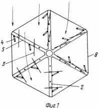
1 shows a carousel wind wheel, top view;
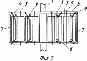
FIG. 2 is a side view of a carousel;
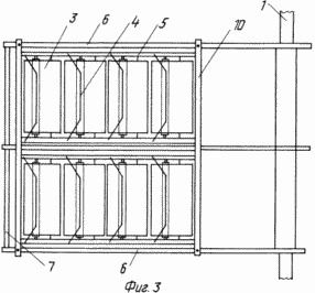
3 shows frame wings with blades in the panels;
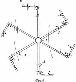
FIG. 4 shows a wind wheel with panels mounted perpendicular to the wheels;
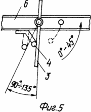
FIG. 5 shows the fixing of the blade rotation limiters on the fly;
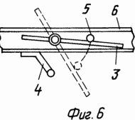
6 shows fastening of stops;
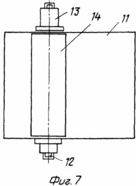
FIG. 7 shows a rotor blade of a carousel (general view); FIG.
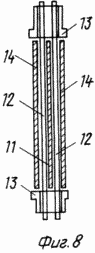
FIG. 8 shows a blade of a wind wheel with an axis made in the form of three bars fixed with profiled plates (cut);
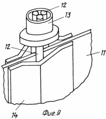
9 shows a blade of a wind wheel with an axis of three bars fixed by profiled plates in assembly;
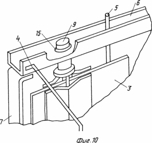
10 shows a swing with a blade assembly.
The claimed carrousel wind wheel comprises radial flaps 2 mounted on a vertical axis 1 with blades 3, paddle stops 4 and stops 5. Each swing 2 is a rigid frame structure made of horizontal rods 6 and vertical stiffeners 7. To enhance the stiffness of the structure, the mahi 2 can be interconnected by inter-mesh fixing bars 8. The flat blades 3 are pivotally pivotable about the axis 9 directly on the horizontal rods 6 or on the panels 10 rigidly attached to the mahs 2. The panels 10 can be mounted both in Plane of the Mach 2, and perpendicular to it, which provides an increase in the power of the wind wheel without significantly increasing its dimensions. The restraints 4 and the stops 5 are fixed to the horizontal rods 6 or to the horizontal members of the panels 10 and further serve as additional stiffening elements. The stops 5 are fixed in the sweeps 2 so that the area of their interaction with the blades 3 lies in the plane of the swing 2 or the panel 10. The limiters 4 are fixed in the sweeps 2 so that the area of their interaction with the blades 3 lies in a plane passing through the axis of rotation 9 at an angle 90 ° to the plane of the fly 2. The blade 3 contains a rectangular sheet 11, the axis 9 is made in the form of three bars 12, one of which is placed on one side of the sheet 11, and the other two on the other, the ends of the rods 12 outside the sheet 11 are placed in Bushings 13, and the bars 12 themselves are fixed on the surface of the sheet 11 by means of profiled plates 14 rigidly fastened to the sheet 11, for example by spot welding. The articulation of the horizontal rod 6 and the blade 3 is achieved by making a vertical hole 15 in the horizontal rod 6, into which the sleeve 13 is inserted.
The work of the rotary carousel is considered in the sequential position of one mah 2 to the air flow from 0 to 270 o . In the swing position 2 from 0 to 180 o, the blades 3 are pressed by the air flow to the stops 5. The uniformity of the torque and its amplification is due to the fact that it is created by the force of the flow pressure on the blade 3, which is the greater, the closer to 90 ° the blade rotation angle 3 to the direction of the air flow, and to the aerodynamic lift (which decreases with approaching the angle of inclination of 90 ° ). With a swinging position 2 of 180 ° , the blades 3 rotate about the axis 9 and, resting on the stops 4, occupy a position with an angle of 90 ° with respect to the swing 2. When turning the swing from 180 to 270 °, the blade 3 rotates the swing 2 due to the lift Force and moment of the force of installation of the blade 3 with displacement from the axis of the swing. To operate the fly 2 from 270 to 360 o, it is possible to force the automatic movement of the stop 5 of the blade 3 from 0 to 45 o in relation to the fly 2. To increase the efficiency of the wind wheel and with a sudden increase in wind, it is possible to automatically change the angle of the limiter 4 of the blade 3 from 90 to 135 O in relation to a fly 2.
At high power it is necessary to increase the dimensions of the wind wheel, for this purpose, the blades 3 are installed in the panels 10, which are rigidly fixed in the mahas 2. This design allows reducing the stiffness requirements of the blades 3, the stops 4 and the stops 5 and using the same typical units for the manufacture of wind Wheels of different power. In addition, a portion of the panels 10 can be mounted perpendicular to the mahams 2 and, thereby, a significant increase in power can be achieved without a noticeable increase in the dimensions of the wind wheel.
CLAIM
1. A carousel wind wheel containing the frame flaps installed on the vertical axis, pivots pivotally mounted in the swings, rotatable and cyclically interacting with the stops and pivot stop limiters fixed to the flaps, characterized in that the blades are flat and the axis of rotation of each blade divides it On unequal parts with the ratio of areas in the range from 10: 1 to 3: 1.
2. A carousel wind wheel according to claim 1, characterized in that each swing comprises rigidly connected horizontal rods and vertical stiffeners.
3. Carrousel wind wheel according to claim 1 or 2, characterized in that the blades are mounted hingedly in panels rigidly fixed on the swings.
4. Carousel wind wheel according to claim 3, characterized in that in each panel there are several blades.
5. Carrousel wind wheel according to claim 3 or 4, characterized in that a part of the panels in the mahas is installed perpendicular to the plane of the fly.
6. Carrousel wind wheel according to one of claims 1 and 2, characterized in that each stop and each blade rotation stopper is fixed between the horizontal rods of the blade and is installed parallel to the axis of rotation of the blade, the interaction area of the abutment with the blade being in the plane of the blade, and the region The interaction of the blade with the blade rotation stopper - in a plane passing through the axis of rotation of the blade at an angle of 90 ° to the plane of the blade.
7. Carousel wind wheel according to one of the claims 3 to 5, characterized in that each stop and each blade rotation stopper is fixed to the panels and installed parallel to the blade rotation axis, the interaction area of the abutment with the blade being in the panel plane, and the blade interaction area With blade stopper - in the plane passing through the axis of rotation of the blade at an angle of 90 ° to the plane of the panel.
8. Carousel wind wheel according to claim 6 or 7, characterized in that the blade interaction area with the blade stop and stopper is 0.5D to 0.9D from the axis of rotation of the blade, where D is the distance from the rotation axis to its most A remote edge from this axis, wherein the interaction of the abutment and the limiter with the blade occurs over the entire width of the blade.
9. A blade of a carousel wind wheel comprising a rectangular sheet fastened to an axis, characterized in that the axis is fixed to the sheet with a distance from the edge by 1/10 ... 1/3 of the length of the blade.
10. A blade according to claim 9, characterized in that the axis is made in the form of three bars, one of which is located on one side of the sheet, and the other two on the other hand, the ends of the bars outside the sheet are enclosed in cylindrical bushings having an internal diameter of ![]() , Where 2R is the diameter of the rod.
, Where 2R is the diameter of the rod.
11. Vane according to claim 10, characterized in that the bars are fixed on the sheet surfaces by means of profiled plates fastened to the sheet
print version
Date of publication 30.01.2007gg
![]()

Comments
When commenting on, remember that the content and tone of your message can hurt the feelings of real people, show respect and tolerance to your interlocutors even if you do not share their opinion, your behavior in the conditions of freedom of expression and anonymity provided by the Internet, changes Not only virtual, but also the real world. All comments are hidden from the index, spam is controlled.