| section Home
Production, Amateur Radio amateur Model aircraft, rocket- Useful, entertaining |
Stealth master
Electronics Physics Technologies invention |
space Mystery
Earth Mysteries Secrets of the Ocean Stealth section Map |
  |
| Use of material is permitted for reference (for websites - hyperlinks) | |||
Navigation: => |
Home / Products Patents / In the section of the catalog / back / |
|
INVENTION
Russian Federation Patent RU2132483
![]()
Automatic wind-driven generator
Name of the inventor: Lebedev VN .; Golofaev VM .; Grips LG
The name of the patentee: Scientific Research Institute of Radio
Address for correspondence: 125190, Moscow, Leningradsky Prospekt 80, of Radio Research Institute, Director Vladimir Gruzdev, the patent department
Starting date of the patent: 1996.07.04
Automatic wind-driven generator is designed for independent power facilities devices located in remote and inaccessible places, and individual consumers, to which the supply of electricity from the unprofitable network and fuel delivery for diesel-stations is associated with high costs. Achieved technical result in that the device comprising mounted on a common rotor of the wind turbine and the system excitation electric machine having n-phase power windings on the stator which is connected through a rectifier and a first key from the inverter and energy storage, the controller and the second switch is further provided with a controlled inverter, inversion element, sensors of wind direction and speed, position sensor, connected to a common rotor. Sensor outputs are connected to the outputs of the controller. The first output of the controller is connected to the control input of the first key itself, and the second - through an inversion element. The second output controller coupled to a first control input of the inverter, a second input coupled to an output energy storage device, and output through the second switch is connected to the m-phase n-phase armature winding. Such implementation of wind-driven generator will improve its effectiveness due to optimum performance: the amount of electricity generated in the used wind speed range, the uniformity of the distribution of electricity generated, minimal aerodynamic drag of a wind turbine at Burevoi winds, with the exception of idling, energy-saving and mobile launch.
DESCRIPTION OF THE INVENTION
The invention relates to engines, and more particularly to a wind turbine, and can be used in devices of independent power facilities located in remote and inaccessible places, and individual consumers to which the mains electricity supply is unprofitable, and fuel delivery for diesel-stations involves large cost.
Wind-driven generator using a renewable source of energy - wind or air flow.
Known gearless wind turbine comprising a wind turbine is connected directly to the magneto AC generator formed as separate segments, with the excitation system on the rotor. The output of the generator via the controlled rectifier and inverter connected to a controllable load / Kopylov IP, Liadov TV Gearless wind generators. Coll. scientific papers Hydroproject, 1988, vol. 129, p. 170 - 174 /.
Wind turbines has increased reliability, since generator made by circuit with contactless electric reduction. However, the most efficient it can be used only in the automatic wind-driven generator.
Known automatic wind power plant comprising vertikalnoosevoy wind turbine equipped with a rotor Savonius starter, generator, rectifier, motor starters, wind speed sensors and speed controller / N. Erickson, J. Ottoson., T. Wolpert, control system based on a microprocessor in order to optimize the power output wind farm. Division "Erickson" electricity distribution company, 612 525, Stockholm, Sweden 1982 /.
However, at high wind speeds Savonius rotor acts as an air brake, which reduces the utilization of wind energy, and hence its efficiency.
The closest to the proposed technical solution is a wind-driven generator comprising a rotor mounted on a common drive system of a wind turbine and electric machine having n-phase coil of the armature on the stator, and a rectifier connected across the first inverter switch and power storage unit, the controller, the second switch /a.s . USSR N 1746057, cl. F 03 D 9/02 /.
However, its efficiency is not sufficient, because in automatic mode does not provide optimum performance:
- The amount of electricity generated in the wind speed range used;
- Uniformity of distribution of electricity generated by the wind flow velocity;
- Minimum aerodynamic drag of a wind turbine at Burevoi winds;
- The presence of the idle rotation;
- Energy saving and mobile launch.
The task to be solved by the invention is to increase efficiency of wind-driven generator by improving the performance characteristics, including:
- Increase in the number of electricity generated by expanding the range of speeds used by the winds,
- Improving the uniformity of the distribution of electricity generated by the velocity of the wind flow,
- Ensure a minimum of aerodynamic drag of a wind turbine at Burevoi winds
- The exclusion of idling,
- Energy saving and mobile launch.
The invention consists in the fact that the wind-driven generator comprising a wind turbine, the electrical machine with the excitation system having n-phase coil of the armature on the stator, to which via a rectifier and a key connected inverter and energy storage unit, the controller is provided with an additional controllable inverter element inversion sensors wind direction and speed, and rotor position sensor, connected to each other and with the aforementioned elements such that at a certain ratio of external factors the electrical machine is switched alternately in the motor, the regenerative modes of operation, but also creates the necessary vector magnetomotive force of the armature winding, that provides improved performance and efficiency of wind-driven operation.
The technical results which can be obtained by carrying out the present invention are:
- Increasing the power generation amount
- Improving the uniformity of the distribution of electricity generated by the velocity of the wind flow,
- Minimum aerodynamic drag of a wind turbine at Burevoi winds
- The absence of idling, and as a result - an increase in the resource,
- Energy saving and mobile launch.
The drawing shows a block diagram of a wind-driven generator.
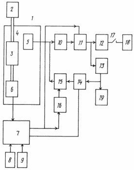 |
Wind-driven generator comprising mounted on a common rotor of one wind turbine 2 and the excitation three electric machine system 4 having n-phase coil 5, armature and located on the stator of the electric machine 4, which is performed by non-contact circuit with electric reduction, and can operate either as a generator or motor. With a total rotor 1 has a connection Sensor 6 position. Communication may be either mechanical or optical or other physical principles on, but so that there is no wired connection to the rotating parts. The sensing elements of the sensor 6 are located on the stator of the electrical machine 4. The output of the sensor 6 are connected to the first input of the controller 7, which may be either based on a microprocessor or microcomputer, or a high-power plants based on a personal computer configuration truncated. The second input of the controller 7 connected to the output of the sensor 8, the wind direction, and the third input - output of the sensor 9 with wind speed. The sensors 8 and 9 must be placed so that the wind turbine does not affect their work. Wind speed sensor 9 is suitable for a modern version of the electronic sensing element. Polyphase winding 5 having n-phases, may be split and included at the discretion of the developer, or the scheme n-phase star or n-polygon phase, or a combination of them. The n-phase winding, a group of m windings, where m is less than n. In practice, it is necessary to choose the optimal m is not more than three, and connect the windings in a "triangle" to reduce the reactance when running in motor mode. |
Outputs n-phase winding 5 are connected to the inputs of the rectifier 10, the output of which through the first switch 11 is connected to the input of inverter 12 and drive 13 energy coupled output to the second control input inverter 14 connected to output through the second switch 15 with m inputs n-phase winding 5.
The first output of the controller 7 is connected to the control input of the first key 11 itself, and the second key - through an inversion element 16. The second output of the controller 7 is connected to the first control input of the inverter 14. A switch 17 is connected power consumer 18, working on direct current. energy consumers, working on direct current, can be connected to the output of the rectifier 10 or 13 energy storage. In particular, the energy storage device may be connected directly to the voltage converter 1 for wind-driven power duty equipment.
Wind-driven generator works as follows
Since wind velocity sensor signal 9 to the controller 7. If, within the time t min corresponds to the wind speed specified value v min, controller 7 outputs the first output signal which is supplied to first switch 11 and closes it, and through an inversion element 16 opens the second 15. The key position sensor 6 outputs a signal to the controller 7 on the overall position of the rotor 1. The controller 7 outputs the second output of the control input signal managed inverter 14, on which 13 of the DC power storage voltage at the output of the inverter formed managed m-phase AC voltage. This voltage is supplied to the m inputs n-phase windings of the armature 5, the magnetomotive force vector which has the greatest disagreement with the vector of the magnetomotive force generated by the excitation system 3. The electrical machine 4 acts described above is translated into motor mode and starts the general rotation of the rotor 1. By achieving numbers total revolutions of the rotor 1 corresponding to the initial number of operating wind turbine speed controller 7 based on the information received from the position sensor 6 changes the signal at its first output, to which first switch 11 opens and closes the second switch 15. As a result of these steps, the electric machine 4 transferred to generator mode. The alternating voltage with n-phase winding 5 is supplied to the rectifier input 10 and then through the first key on the drive consists of 13 energy and the inverter 12, which converts the DC voltage to AC with the desired parameters and tolerances of frequency, voltage, allowable current consumption and phase shifts between stresses.
In the case when the wind speed reaches Burevoi values set by the controller 7, the latter on a signal from the sensor 9, the wind speed, the signals from the sensor 8, the wind direction and sensor 6 are common rotor 1 computes the mismatch and outputs a signal of control action on the second output to the input managed inverter 14, and outputs the first output signal for closing the key 11, the key opening 15, whereby the electrical machine in motor mode translated, to position the wind turbine expands with minimal aerodynamic drag and holds it in this position for a tracking mode, the wind direction.
The user 18, who works on alternating current, can be connected to the inverter 12 through a switch 17. The output drive 13 can be either directly or via an additional switch connected to appliances operating on direct current. In the particular case, it may be a voltage converter for power control equipment and the first duty of the equipment: the position sensor, wind direction and speed controller, which have low power consumption.
CLAIM
Automatic wind-driven generator comprising mounted on a common rotor of the wind turbine and the system excitation electric machine having n-phase power unwinding the armature on the stator, connected via a rectifier and the first key to the inverter and energy storage unit, the controller, the second switch, characterized in that it is provided with a controlled inverter, element inversion sensors wind speed and direction, the position sensor connected to the common rotor, and output - with a first input controller coupled to the second and third inputs respectively to the outputs of the sensor direction and the wind speed sensor, the first output of the controller is connected to the control input of the first switch directly and the second - after the inversion element, the second controller output is connected to the first control input inverter, a second input coupled to an output energy storage device, and output through the second switch is connected to the m-phase n-phase armature winding.
print version
Publication date 30.01.2007gg
![]()

Comments
Commenting, keep in mind that the content and the tone of your messages can hurt the feelings of real people, show respect and tolerance to his interlocutors, even if you do not share their opinion, your behavior in terms of freedom of speech and anonymity offered by the Internet, is changing not only virtual, but real world. All comments are hidden from the index, spam control.