| section Home
Production, Amateur Radio amateur Model aircraft, rocket- Useful, entertaining |
Stealth master
Electronics Physics Technologies invention |
space Mystery
Earth Mysteries Secrets of the Ocean Stealth section Map |
  |
| Use of material is permitted for reference (for websites - hyperlinks) | |||
Navigation: => |
Home / Products Patents / In the section of the catalog / back / |
|
INVENTION
Russian Federation Patent RU2235901
![]()
Wind turbine
Name of the inventor: Kolesnikov VD (RU); Kolesnikov DV (RU); Kolesnikov, PV (RU)
The name of the patentee: Valery Kolesnikov (RU); Kolesnikov Dmitry V. (RU); Kolesnikov Pavel V. (RU)
Address for correspondence: 12900, Saratov, g.Volsk, Proletarian lane 9, kv.32, V.D.Kolesnikovu..
Starting date of the patent: 2001.07.06
The invention relates to wind power engineering and can be used to drive the movement of working bodies generators, pumps and other mechanisms. The technical result is to increase the energy efficiency of the wind and the creation of a wind turbine capable of independently dispersed by aerodynamic lift blades. Wind turbine comprises a shaft attached to it and the radial yoke pivotally associated profiled blades. The axis of the hinges of each blade offset from the center of gravity of the blade airfoil and focus it toward the toe, and the blades are mounted in hinges with the ability to rotate freely within the sectors limited by mechanical stops.
DESCRIPTION OF THE INVENTION
The invention relates to wind power - wind power to drive the movement of the working bodies of power generators, pumps and other machinery.
Known wind turbines with a vertical axis of rotation have an advantage over vane wind turbine with a horizontal axis of rotation, as it does not require its orientation working member - of the rotor with respect to the airflow. In such engines use lift blades - wing fixedly attached to the rotor to create the rotor shaft torque. This so-called Darrieus wind turbines systems (Frenkel Shefter use of wind energy. M .: Energoizdat. 1983. p.71, 72). The main drawback of these engines is the need for a forced promotion of the rotor and then the rotor starts to give myself energy. This is due to the fact that when small numbers Z (the ratio of the circumferential blade speed to wind speed) is only a small part of the circular path of the blade movement conditions exist for unseparated flow. For example, when Z = 1 there are only such conditions 8% trajectory. Therefore, the scope of the Darrieus wind turbine system is limited, as a rule, work with power generators that can be used in the start mode as motors (RS Abdrakhmanov, Yu Perevedentsev Renewables. Kazan, a publishing house in Kazan University, 1992, with .77, 78).
There are technical solutions, in which attempts were made to create a wind turbine with a vertical axis of rotation, capable of self-accelerate to operating speed. In such wind turbines provided the use of automatic control systems (the CAP), the position of the blades to the oncoming flow (Inventor. 1987, N 9. C.8, 9). CAP comprises speed measuring device and the airflow guiding device and computer system of forced rotation of blades in the position in which the moment of the aerodynamic forces acting on a wind turbine rotor, has a maximum value. Application of the CAP, according to the authors, can be justified only on the high-power wind turbines (1000 kW) for economic reasons. It is also known solution (AS SU 1456638 A1) selected by the authors as a prototype, in which the role of regulator blades position relative to the airflow perform aerodynamic surface - stabilizers, pa fixed blades. Themselves blades mounted on the rotor traverses hinged and the free angular movement are held by elastic elements with variable stiffness by a centrifugal regulator. Wherein the axis about which the angular displacement may blades runs through the center of gravity blade. For this wind turbine design provided counterweights, balancing the weight of stabilizers. The main drawback of the prototype the authors believe that regulators, fulfilling its role in the acceleration of the rotor, aerodynamic brakes are working with rotor speeds, thereby reducing the utilization of wind energy. Furthermore, the presence of hinge joints in the construction of the elastic elements with adjustable stiffness, rigidity centrifugal regulators, stabilizers complicates the wind turbine, it impairs economic characteristics. Therefore the problem to be solved by the proposed invention is to provide a wind turbine with vertical axis of rotation, using aerodynamic lift blades capable of independently dispersed. Another object of the invention is to increase the rate of wind energy as compared with the prototype.
Solving these problems is achieved by providing the rotor with a freely pivoting about the longitudinal axis of the shaped blade (having a cross-sectional airfoil) - within sectors with angles of 60 °. Moreover, the angular displacement axis of the blade, which hinge axis and each blade is offset relative to the center of gravity of the focus and the blade airfoil profile in the direction of the toe. The role of the regulator of the current position of the blade in relation to the oncoming flow of the rotor on the side facing the wind carries the interaction of aerodynamic forces and moments of the centrifugal. This makes it possible to renounce the use of stabilizers and thereby eliminate the energy losses associated with aerodynamic stabilizers on the operating speeds of a wind turbine.
On the side of the rotor facing away from the wind, there are no conditions for the implementation of this method with respect to the blade position control flow aerodynamic moments and centrifugal forces are not mutually balanced. The blades, pressing the stops, occupy the same position as the rotor blades fixed to fixed.
 |
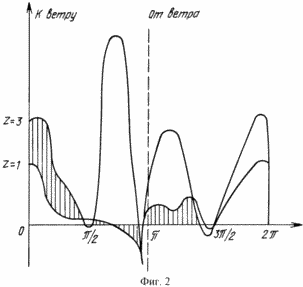 |
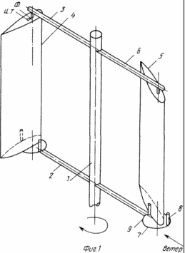
1 shows, the invention - a wind turbine with a vertical axis of rotation, where the following notation: 1 - the rotor shaft of a wind turbine; 2, 3 - the radial yoke; 4, 5 - blade shaped; 6 - hinge bearing units; 7 - plates with mechanical stops; 8, 9 - mechanical stops; CG - center of gravity of the wing; F - the focus of the airfoil. Figure 2 shows the calculated detailed diagrams dimensionless moments of forces for one wing of the entire circular path of motion at Z = 1 and Z = 5.
On the hub shaft 1 fixed vertical radial yoke 2, 3, which together with the shaft and shaped blades 4, the rotor 5 is formed, held upright braces. The blades are fixed to the ends of the traverse by means of articulated bearing units 6 to be freely rotatable relative to the longitudinal axes, within a sector of 60 °, wherein the rotation axis is offset from the focus line and the blade center of gravity in the direction of the profile of the sock so that the condition of equality of the moments of inertia forces and aerodynamic. On the lower beam fixed mobile base - plate with 7 stops 8, 9, limits the resolution of the sector rotation of the blades.
From standstill of a wind turbine rotor is displayed moments of force associated with the difference between the dynamic pressure of the wind pressure on the nose and tail sections of the blades when the rotor has two blades and are positioned so that the blade, located on the side of the rotor facing towards the wind reaches stop 9. Further rotation of the rotor leads to the fact that under the action of aerodynamic forces one of the blades, turning in hinges reaches the stop 9 and the rotor begins to rotate. On the side of the rotor facing away from the wind, with Z <1 based on the blades 8 and rests mainly directed to the total vector of the velocity head with supercritical angles of attack, however, the direction of the aerodynamic forces moments remains positive, i.e. It does not oppose the rotation of the rotor. Further increase in the rotor speed causes an increase in the moments of the aerodynamic forces on the entire circular path of movement of the blades. On the side of the rotor facing into the wind, the position of the blade in relation to the vector velocity head is defined by torques of aerodynamic and centrifugal. On the rotor side facing away from the wind, the blade 8 is pressed against the stop.
Upon reaching the angular velocity at which the Z = 3, the entire blade trajectory pressed by centrifugal forces to the stops 8 and wind turbine operates as a conventional Darrieus wind turbine system. However, unlike the prior art in the present invention, there is no loss of energy associated with aerodynamic stabilizer that improves the utilization of wind energy as compared with the prototype.
Deployed diagram dimensionless rotor power points for one blade at Z = 1 and Z = 5 are shown in Figure 2. To calculate the moments of the forces used in the polar circle blow wing with a symmetrical profile. Control of the rotor speed by changing the position of moving plates 7. This achieves a change in the position and stops 8 respectively - the blades located on the rotor side facing away from the wind. Removal of the stop 8 from the center of the rotor, first causes a decrease of the angle blade attack and then transfer it to a negative value at which the torque transmitted by the vane rotor becomes negative, as a result of the speed increase in dependence on the position of the stop 8 or stops, either the rotor is slow down the rotation. Rotating the focusing plate 8 7 90 ° relative to the wing oscillation axis of the rotor will stop.
CLAIM
Wind turbine comprising a shaft secured thereon, radial traverse hingedly associated profiled blades, characterized in that the hinge of each blade axis displaced from the blade's center of gravity and the focus of the airfoil toward its toe, and the blades are mounted in hinges with the ability to rotate freely in within sectors, limited by mechanical stops.
print version
Publication date 30.01.2007gg
![]()

Comments
Commenting, keep in mind that the content and the tone of your messages can hurt the feelings of real people, show respect and tolerance to his interlocutors, even if you do not share their opinion, your behavior in terms of freedom of speech and anonymity offered by the Internet, is changing not only virtual, but real world. All comments are hidden from the index, spam control.