| section Home
Production, Amateur Radio amateur Model aircraft, rocket- Useful, entertaining |
Stealth master
Electronics Physics Technologies invention |
space Mystery
Earth Mysteries Secrets of the Ocean Stealth section Map |
|
| Use of material is permitted for reference (for websites - hyperlinks) | |||
BRIEF DESCRIPTION OF THE DRAWINGS wind turbines (wind turbines)
The above object and other features and advantages of the present invention will become more apparent upon reading the following detailed description in conjunction with the consideration of the drawings, among which:
 |
 |
 |
 |
1 is a front view showing an example of the windmill wings according to the present invention;
2 is a cross section along line A-A of Figure 1;
3 is a cross section along line B-B in Figure 1;
4 is a perspective view, partially broken away, showing an example of the wind pressure plate regulation in accordance with the present invention;
 |
 |
5 is a front view illustrating the means for measuring the wind direction and wind force sensing means according to the present invention;
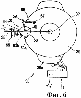
6 is a top view illustrating the means for measuring the wind direction and wind speed measurement means 5;
 |
 |
 |
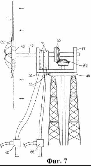
7 is a schematic view of a wind turbine wing in the assembled state in accordance with the present invention;
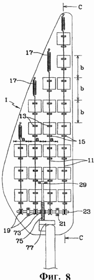
8 is a front view illustrating another example of the windmill wings according to the present invention;
9 is a cross-sectional view taken along line C-C 8;
 |
 |
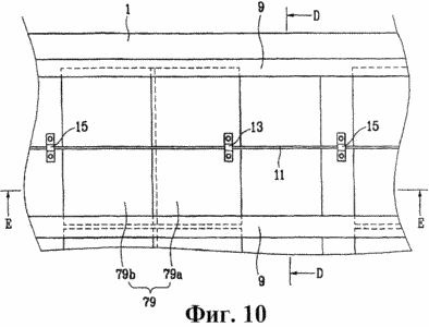
10 is a plan view illustrating another example of the wind pressure plate regulation in accordance with the present invention;
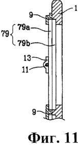
11 is a cross section along line DD 10 illustrating the wind pressure plate adjustment;
 |
 |
 |
12 is a cross-sectional view along line E-E of Figure 10 illustrating a fully open state of the wind pressure plate adjustment;
13 is a cross-sectional view along line E-E of Figure 10, illustrating a primary closing stage of the wind pressure plate adjustment;
14 is a cross-sectional view along line E-E of Figure 10, illustrating a secondary closing stage of the wind pressure plate adjustment;
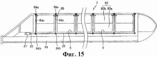
15 is a front view illustrating another example of the windmill wings according to the present invention;
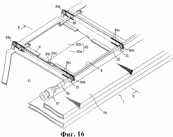
16 is a perspective view, partially broken away, illustrating the wind pressure plate adjustment shown in Figure 15;

17 is a cross section along E-E line of Figure 16 illustrating a fully closed state of the wind pressure plate adjustment;

18 is a cross section along E-E line of Figure 16, illustrating a primary opening stage of the wind plate pressure regulation;

19 is a cross section along E-E line of Figure 16, illustrating a secondary opening stage of the plate to the wind pressure regulation;
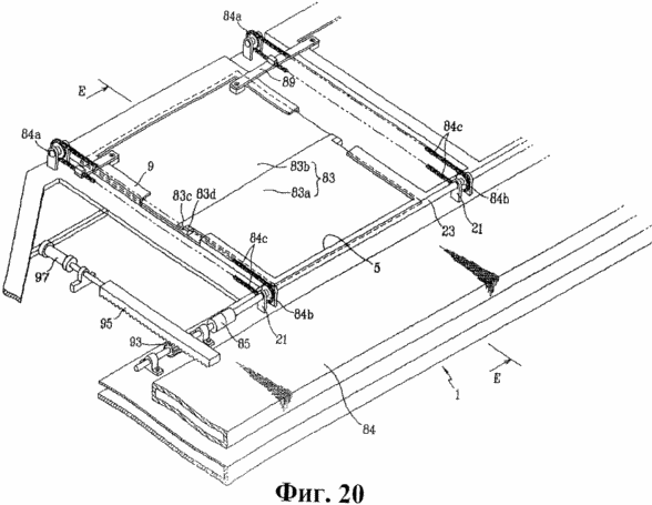
Figure 20 is a perspective view, partially broken away, illustrating the wind pressure plate adjustment shown in Figure 15;
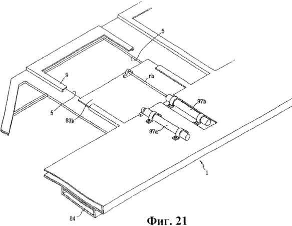
21 is a perspective view, partially broken away, illustrating the wind pressure plate adjustment shown in Figure 15;
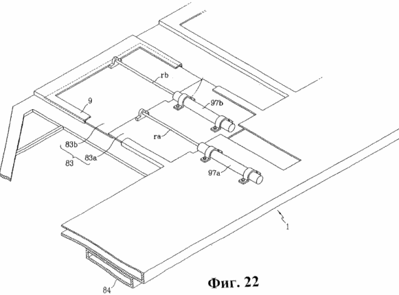
22 is a perspective view, partially broken away, illustrating the wind pressure plate adjustment shown in Figure 15;
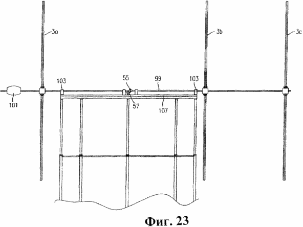
Figure 23 is a side view showing an example of a wind power generating apparatus according to the present invention;
 |
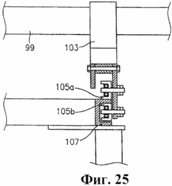 |
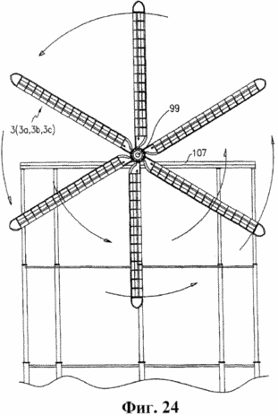
Figure 24 is a front view illustrating a left portion of the device in a wind power Figure 23;
Figure 25 is a sectional view illustrating the shaft supporting member shown in Figure 23;
 |
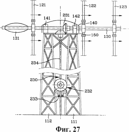 |
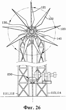
Figure 26 is a rear view illustrating another example of the wind power generating apparatus according to the present invention;
Figure 27 is a side view illustrating an example of a wind power generating apparatus shown in Figure 26;
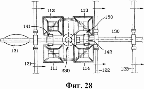
Figure 28 is a plan view showing an example of wind power generating apparatus shown in Figure 26;
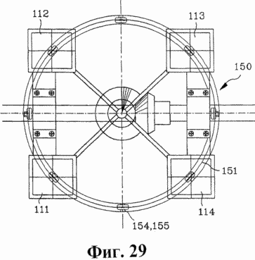
29 is a plan view illustrating the rotary device shown in Figure 28;
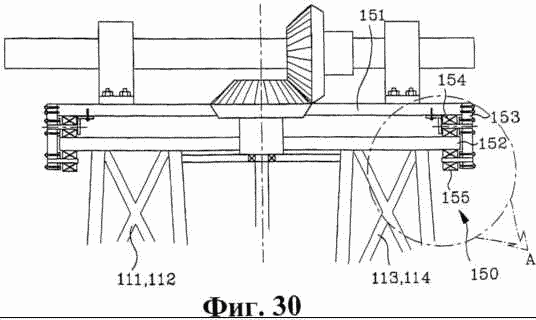
Figure 30 is a side view illustrating the rotary device shown in Figure 28;
 |
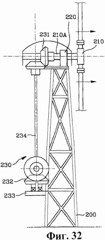 |
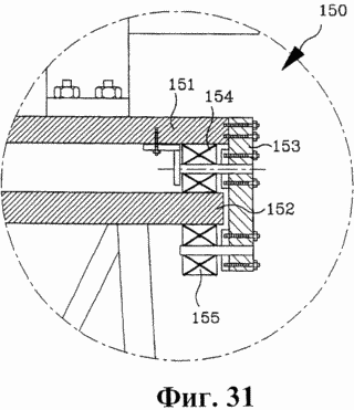
Figure 31 is an enlarged sectional view corresponding to a portion "A" Figure 30, and
Figure 32 is a side view illustrating the wind power generating apparatus as a whole.


Comments
Commenting, keep in mind that the content and the tone of your messages can hurt the feelings of real people, show respect and tolerance to his interlocutors, even if you do not share their opinion, your behavior in terms of freedom of speech and anonymity offered by the Internet, is changing not only virtual, but real world. All comments are hidden from the index, spam control.