| section Home
Production, Amateur Radio amateur Model aircraft, rocket- Useful, entertaining |
Stealth master
Electronics Physics Technologies invention |
space Mystery
Earth Mysteries Secrets of the Ocean Stealth section Map |
  |
| Use of material is permitted for reference (for websites - hyperlinks) | |||
Navigation: => |
Home / Products Patents / In the section of the catalog / back / |
|
INVENTION
Russian Federation Patent RU2151322
![]()
Wind turbine for wind turbines
Name of the inventor: A. Aliyev
The name of the patentee: Dagestan State University
Address for correspondence: 367025, Makhachkala, ul. M. Hajiyev 43a, DSU, Intellectual Property Division
Starting date of the patent: 1999.01.18
The invention relates to wind power engineering, namely to the devices for converting wind energy into electrical energy. The technical result is to stabilize the output shaft speed irrespective of wind speed is achieved in that a wind turbine comprising a housing, a shaft and a wheel with blades mounted rotatably about their axes at the root parts of which are fixed arms with rollers that interact with the disk rigidly fixed to vane and pivotally mounted on the shaft, the wind turbine is further provided with a centrifugal speed controller, a platform mounted for vertical movement relative to the disk, and the rod cooperating with the platform and the slide of the centrifugal speed controller, a and inclined planes with which a platform pivotally connected to the disk while the disk platform overlaps half border section coincides with the plane weathervanes
DESCRIPTION OF THE INVENTION
The invention relates to a device for converting fluid energy and can be used in Wind power.
A device for fluid power, comprising a paddle wheel mounted rotatably on their axes. Each blade shaft is divided into two portions with unequal areas [1].
However, the known device only works under the water at a constant direction of water flow. This limits its applicability, in particular in wind turbines, wherein wind direction frequently changes.
The closest device of the same purpose to the claimed combination of features for the invention is an apparatus for using fluid energy taken as the prototype [2].
Prototype comprises a shaft rotatably mounted on the base, fixed to the shaft body with flat blades, rotating about axes provided with levers. At the ends of levers mounted rollers. The device is provided with a vane and rigidly connected to it a cam plate pivotally mounted on the shaft and interacting with rollers. Levers with rollers interact with a longitudinal surface of the cam plate, and as a result the blade forcibly change their orientation.
The obstacles to achieve the said below technical result, when using the known device adopted as prototype, is the fact that the shaft rotation speed is proportional to wind speed, which varies widely. This limits its applicability in generators.
The task of the claimed invention is to synchronize the rotational speed of the output shaft of a wind turbine.
The technical result of the invention consists in that the stabilizing engine speed regardless of wind speed change range. This extends the capability of its application in the Wind power generators.
Said technical result in the implementation of the invention is achieved in that the wind turbine comprising a housing, a shaft and a wheel with blades mounted rotatably about their axes. At the roots of the axes of the fixed arms with rollers cooperating with the disc, which is rigidly fixed vane and pivotally mounted on the shaft. The following additional features are introduced.
Wind turbine provided with a centrifugal speed controller, a platform mounted for vertical movement relative to the drive rod and interacting with the platform and slider centrifugal speed controller.
Furthermore, the engine is provided with inclined planes, by which the platform is pivotally connected to the disk platform thus overlaps a half of the disc, the border section coincides with the plane of the wind vane.
 |
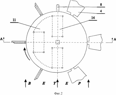 |
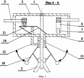
FIG. 1 shows a wind turbine structure in section A-A. FIG. 2 - a top view of FIG. 1.
Wind turbine 1 comprises a shaft, rotatably mounted on the base 2 fixed to the shaft body 3 with four flat blades, rotating about axes 5, 6 provided with levers on which the ends of the rollers 7. In this set is provided with a vane motor 8 and is rigidly connected therewith plate 9 pivotally mounted on the shaft and interacting with rollers. Furthermore, a wind turbine includes a centrifugal speed controller 10, a platform 11 mounted for vertical movement relative to the drive rod 12 and cooperating with the slider 13, the centrifugal speed controller. The engine is provided, and the inclined plates 14 by which the platform is pivotally connected to the disk.
Wind turbine works as follows
Fixed base 2 provides the necessary height of the wind turbine location for the safe and efficient operation.
The shaft 1 is pivotally mounted on the base 2, a vertical position and the possibility of free rotation.
Engine housing 3 is fixedly mounted on the shaft. This can be achieved by the key, pin, or their spline connections. Thus, the housing 3 is rotated together with the vertical shaft 1 relative to the fixed plate 2.
On the periphery of the housing at the same distance from each other are pivotally mounted at least three blades 4. FIG. 1, the wind turbine has six blades set at 360 o / N = 60 degrees, where N - number of blades.
Each blade has its axis 5. Axis vanes 4 divide the plane into two portions with unequal areas. Axis mounted on the housing 3 pivotally radial direction and are located in a plane perpendicular to the shaft (see. Fig. 2).
The blades are provided with arms 6 enshrined among their ends on the axes 5 at the root portion thereof. On the other end of the lever mounted rollers 7.
Wind turbine is equipped with a weather vane 8, rigidly connected with the disk 9.
The disc 9 is pivotally mounted concentrically on the shaft. It is rotatable around an axis together with the vane when the direction of wind.
The disc 9 is pivotally mounted to base 11 for vertical movement relative to the parallel drive.
To this are three inclined plates 14. With the flat joints (hinges) plate secured to the platform and disk. When they form a parallelogram connection. When changing the inclination of the plate in the range x = 0-45 o platform moves from the lowest position coincides with the plane of the disk, up to the top.
The line separating the interface disc and the edges of the platform, the wind vane coincides with the plane 8. The pair of inclined plate 14 is mounted in said plane. The third plate forms an opposite side of the parallelogram.
Under the influence of the pressure difference of the wind stream into two asymmetrical halves with blades levers rollers cooperate with the upper surfaces of the platform and disk.
Vane 8 oblique wind pressure flow is set parallel to the flow and orients the disc 9 with the platform 11 with inclined plates 14, mounted in a diametrical plane of the disc coincide with the plane of the wind vane, i.e. wind flow direction.
Levers with rollers as a result of interaction with the surfaces of the platform 11 and disk 9 forcibly change the orientation of the blades 4. The vanes via lever 6 cooperating with the platform to the right of the center plane, are perpendicular to the flow, and the left blade, interacting with the disk surface, - parallel flow . With this arrangement the wind wheel blades acquires left (counterclockwise) rotation when viewed from above in FIG. 2.
The blades with each rotation of the wind wheel, turning around their longitudinal axes in the range 0-90 o, take the most advantageous position and create the maximum torque.
In order to synchronize the speed of rotation of the propeller shaft 1 mounted centrifugal speed regulator 10. With an increase in wind speed velocity of rotation of the shaft 1 increases and the slider 13 moves down a centrifugal regulator. In the slide groove 13 includes L-shaped rod head 12 (see. FIG. 2).
The rod has a rectangular cross-section can move vertically with the opening through the disk. The other end of the rod rests on the platform 11. Thus, the slide of the centrifugal speed controller 10 through the rod 12 interacts with the platform 11.
In light winds the slider 13 and thus, the platform 11 is in the uppermost position. Interaction with levers platform 6 in this case forces the plane of the blades to the right of the center plane (see. FIG. 2) perpendicular to the flow of the wind.
With increasing wind speeds of shaft rotation speed increases, and the slide of the centrifugal speed controller 10 moves down. This results in a corresponding displacement of the down rod 12 and interacts with the platform 11.
The interaction with a platform mounted levers blade plane at an angle to the direction of wind flow.
The effective area of the blades, creating a moment of rotation is reduced, which reduces the engine speed and velocity.
Thus a dynamic equilibrium in which the relative wind wheel rotates at a constant rotation speed regardless of the speed change range.
By varying the weight and dimensions of centrifugal weights shoulders speed controller, but also the relative lifting platform can reach the different speeds and precision synchronization turbine rotation.
The proposed wind turbine design improves sensitivity to weak wind flow and performance of the device.
Synchronization propeller rotational speed increases the range of possible propeller applications, can be used in Wind power generators.
INFORMATION SOURCES
1. USSR Patent N 11093. M.kl 5 F 03 B 3/14, 1926
2. A. Aliyev, Chelyaba IM, Chumakov SA A device for converting fluid energy. Russian patent under the application 4897568/29, 1990 (prototype).
CLAIM
Wind turbine comprising a housing, a shaft and a wheel with blades mounted rotatably about their axes at the root parts of which are fixed arms with rollers that interact with the disk, which is rigidly fixed vane and pivotally mounted on the shaft, characterized in that is further provided with a centrifugal speed controller, a platform mounted for vertical movement relative to the disk, and the rod cooperating with the platform and the slide of the centrifugal speed controller, a and inclined planes, by which the platform is hingedly connected with a disc, while the platform covers the half of the disk, the boundary section of which coincides with the plane of the wind vane.
print version
Publication date 31.01.2007gg
![]()

Comments
Commenting, keep in mind that the content and the tone of your messages can hurt the feelings of real people, show respect and tolerance to his interlocutors, even if you do not share their opinion, your behavior in terms of freedom of speech and anonymity offered by the Internet, is changing not only virtual, but real world. All comments are hidden from the index, spam control.