| section Home
Production, Amateur Radio amateur Model aircraft, rocket- Useful, entertaining |
Stealth master
Electronics Physics Technologies invention |
space Mystery
Earth Mysteries Secrets of the Ocean Stealth section Map |
  |
| Use of material is permitted for reference (for websites - hyperlinks) | |||
Navigation: => |
Home / Products Patents / In the section of the catalog / back / |
|
INVENTION
Russian Federation Patent RU2281411
![]()
WIND POWER PLANT
Name of the inventor: Mironov, Nikolai Ivanovich (RU)
The name of the patentee: Nikolai Mironov (RU)
Address for correspondence: 690000, Vladivostok, st. Uborevicha 10b kv.5, N.I.Mironovu
Starting date of the patent: 2002.08.07
The invention relates to wind energy and can be used to convert wind energy into electrical energy. The technical result is to increase the capacity of wind turbines. The wind power plant comprises a horizontal platform, simply supported on the rail, with rigidly fixed on it weather vane, the working surface of which passes through the axis of rotation of the horizontal platform. On the platform are fixed shafts, which are put on the radial traverse, traverse ends pivotally connected beams. Beam mounted for reciprocating movement parallel to one another and the working surface of the wind vane, passing through the vertical shafts. Rotary blades are mounted on vertical axes in the reference frames, each of which is rigidly fixed on the beam, the driving connection with an electric operate cantilever beam pivotally connected to the cross-members and transmitting reciprocating inertial element mounted rotatably on horizontal guides the swing frame. Inertial member is provided with ratchet contacting each on the site with the screw shaft surface, divided into two sections, twist which is made in opposite directions.
DESCRIPTION OF THE INVENTION
The invention relates to wind power engineering and can be used to convert wind energy into electrical energy.
Known wind power plant (AS USSR №1451330, cl. F 03 D 7/06, 1989), containing parusoobraznye blades mounted on radial yoke placed on a vertical shaft, and is kinematically connected to an electric generator, the working mechanism of change the area of the blades and the orientation mechanism, in the form of a weather vane.
The disadvantage of this technical solutions - the inability to provide a high power oscillator.
The closest the technical essence is chosen as the prototype (patent of Russia №2002107, cl. 4 MKI F 03 D 3/00, F 03 D 3/06, F 03 D 5/00, F 03, 7/06, 30/10/1993 g) the wind power installation comprising a rotor rotatable relative to the support surface of the horizontal vane platform, rotary vanes forming parusoobraznye plane mounted on vertical axes in the support frames mounted on bogies mounted for reciprocating movement on rails parallel to each other, placed on a shaft fixed on a horizontal platform, radial sliding yoke is pivotally connected to the cart, the kinematic connection formed as a hinged connection with traverse shaft screw surface divided into two regions with a twist opposite direction, the generator is placed on the shaft, the housing generator is hinged on a horizontal platform.
This wind power plant is not without its drawbacks, the main of which - the inability to provide a high power setting, the power limiting on the generator shaft due to the inability to increase operating parusoobraznyh planes because This prevents the possibility of carrying trucks, reciprocating movement along the guide rails.
The technical result is to increase the plant capacity by providing opportunities to increase the power of the generator shaft.
Wind power installation comprising a horizontal platform with a weather vane, a vertical shaft and mounted on it sliding radial traverse hingedly connected with bogies mounted with the possibility of reciprocating movement along the guide, rotating blades mounted on vertical axes in the support part fixed on the trolley, and electric, kinematically connected to the blades with the screw shaft spins opposite direction. When this unit is provided with additional vertical shaft and attached to it an additional radial traverse ends traverse hingedly connected beams mounted with the possibility of reciprocating movement parallel to one another and the working surface of the wind vane, disposed in a vertical plane passing through the vertical shafts, the rotary blades are mounted on vertical axes in the reference frames, each of which is rigidly fixed on the beam, and a kinematic connection with an electric generator is made as a hinged with crossarms cantilever beams transmitting reciprocating inertial element mounted rotatably on horizontal guides the swing frame and provided with a ratchet clutches contacting each portion on its surface with a screw, divided into two sections which twist in opposite directions formed.
Proposed wind power plant is different because you can abandon carts, reciprocating movement of the guides, in addition, the installation is equipped with an inertial element incorporated into the driving connection with an electric generator.
Thus, the inventive wind power installation meets the criterion of "novelty" of the invention.
The wind power plant is illustrated by drawings, where:
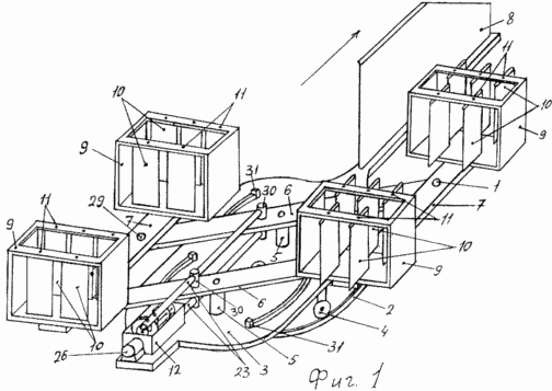
Figure 1 shows a general view of a wind power plant
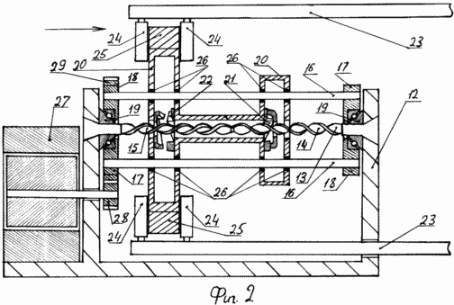
Figure 2 shows a section through the electric generator and the drive to it
Placed on the supporting surface two annular rail, a horizontal platform 3 is provided with four rollers, that is simply supported on two rails.
Along the horizontal axis of symmetry of the platform 3 mounted vertical shafts 5, which is rotatably placed radial crosspiece 6. The beams 7 are pivotally connected to the ends of the traverse and 6 are mounted for reciprocating movement parallel to each other and a weather vane 8, which is fixed to the platform 3 in the vertical plane passing through the pivot axis 6. traverse beams 7 are fixed (beams perpendicular to the direction of movement) the supporting frame 9, which has vanes 10. The vanes 10 are mounted each on a separate pivot shaft 11 so that, depending on the rotation axes 11 form a "continuous sail" when the maximum aerodynamic resistance, or an array of parallel planes when the aerodynamic drag "sail" is minimal. Blade rotation mechanism 10 (not shown) may be formed as a chain drive with the drive gears of the envelope mounted on the axles 11.
The support frame 12 placed on the horizontal platform 3, the shaft 13 is fixedly mounted plate-formed into a helical twist, the shaft 13 is divided into two sections 14 and 15, which is made twist in opposite directions. Horizontal guides 16 are rigidly secured in partitions 17, parallel to each other and the helical surface and form with the latter a rotatable frame 18 mounted on bearings 19. Inertial member 20 is mounted on horizontal guides 16 rotatably and reciprocally movable relative to the plate surface of the shaft 13 and provided with a ratchet to engage each (in the area 14 - sleeve 21, at the site - 15 - sleeve 22) only with its shaft portion 14, 15. Cantilever beams 23 are pivotally connected to cross-members 6 with a reciprocating movement parallel to the working plane weather vane 8, 23 at the ends of the beams are placed rollers 24 in contact with the rim 25 of the inertial member 20 to freely rotate therein latter. The generator 27 is driven to rotate the gears 28 and 29.
In addition, Figure 1 shows limit switches 31, one hinge shafts 30; Figure 2 shows the holes 26 and inertial member 20, which passed into the guides 16 of the swing frame 18.
Wind power installation operates as follows. Weathervane 8 platform provides a turn 3 in the operating position in the direction of the wind (arrow). In this case the supporting frames 9 with blades 10 fixed on the beam 7, parallel to the working plane 8 weathervanes, are deployed perpendicularly to the direction of the wind. To start the installation work sufficiently expand vanes 10 on one of the beams 7 by 90 ° compared with the position of blades 10 on the other beam 7. In this bar 7, "sail" which is perpendicular to the wind direction, will move in the wind direction, and the beam 7 , the blades 10 are deployed parallel to the wind direction, will go in vain against the direction of the wind. When the beams 7 will reach the end, will work 31 limit switches, which include steering gear blades 10, turns them by 90 °. As a result of this work is included in the bar, which was idle, its blades 10 are deployed across the wind direction (the blade 10 of the second beam are deployed along the direction of the wind), then all repeats.
At its rolling back and forth on the shaft 5 traverses 6 is pushed (or pulled by a) cantilever beams 23 and rollers 24 arranged at the ends of cantilever beams 23, interact with the rim 25 of the inertial element 20, so that the inertial element 20, mounted on rails 16, receives pulses from the beams 23 forward (or return) motion, while the ratchet sleeve 21, 22 of the inertial element 20 interact with the surface of the screw shaft 13. When the inertial member 20 is moved in one direction (shown by an arrow in Figure 2) running clutch 21 on the shaft portion 14 and transmits the rotation of the inertial element 20, the sleeve 22 is not working. When traveling in the opposite direction clutch 22, worked previously idle, including the work on the shaft portion 15, the clutch 21 are out of operation. Thus, the inertial element 20 at all times twisted by one side. Cantilever beams 23 make stroke, deviating from the axis of the shaft of the plate 13, the force application point is displaced on the rim 25 of the inertial element 20, in rotating the rollers 24. The rollers 24 at reciprocation cantilever beams 23 move along with the last working plane inertial element 20, passing rolling traverse 6. The inertial element 20, moving on horizontal guides 16, transmits the rotation of the rotary frame 18, mounted on bearings fixed on the frame 19. The partition 17, 18, the gear 29 transmits rotation of the gear 28 fixed to the shaft of the generator 27.
When an excessively large wind flow vane 10 powers in frames 9 are set at an angle to the wind direction, rather than transversely.
The proposed wind power plant can increase the alternator shaft input by allowing a significant increase in the size of workers' sails. "
CLAIM
Wind power installation comprising a horizontal platform with a weather vane, a vertical shaft and mounted thereon a sliding radial traverse hingedly connected with bogies mounted with the possibility of reciprocating movement along the guide, rotating blades mounted on vertical axes in the support part fixed on the trolley, and an electric generator which is kinematically connected to vanes screw shaft with spins opposite direction, characterized in that, in order to increase the power unit is provided with additional vertical shaft and attached to it an additional radial traverse ends traverse hingedly connected beams mounted with the possibility of reciprocating movement parallel to one another and the working surface of the wind vane, disposed in a vertical plane passing through the vertical shafts, the rotary blades are mounted on vertical axes in the reference frames, each of which is rigidly fixed on the beam, and a kinematic connection with an electric generator is made as a hinged with crossarms cantilever beams transmitting reciprocating inertial element mounted rotatably on the horizontal guide frame and provided with a rotary ratchet clutches, each on its contacting portion with the screw surface, divided into two sections which twist in opposite directions formed.
print version
Publication date 23.12.2006gg
![]()

Comments
Commenting, keep in mind that the content and the tone of your messages can hurt the feelings of real people, show respect and tolerance to his interlocutors, even if you do not share their opinion, your behavior in terms of freedom of speech and anonymity offered by the Internet, is changing not only virtual, but real world. All comments are hidden from the index, spam control.