| section Home
Production, Amateur Radio amateur Model aircraft, rocket- Useful, entertaining |
Stealth master
Electronics Physics Technologies invention |
space Mystery
Earth Mysteries Secrets of the Ocean Stealth section Map |
  |
| Use of material is permitted for reference (for websites - hyperlinks) | |||
Navigation: => |
Home / Products Patents / In the section of the catalog / back / |
|
INVENTION
Russian Federation Patent RU2057843
![]()
DAM Hydro power plants
Name of the inventor: Susanin Vladimir Maksimovic
The name of the patentee: Susanin Vladimir Maksimovic
Address for correspondence:
Starting date of the patent: 1992.09.01
Use: in construction of hydropower at ensuring the preservation of the natural ecological state. The inventive hydroelectric power plant contains 1 conduit passing through the open computer room 2, while in the engine room 2 in conduit 1 arranged hydraulic units 6 and its input and output sections are connected to the watercourse and are equipped with shut-off valves 3. At the top of the conduit 1 made a siphon priming outlet 4 is located with a sealed lid 5. with closed valves 3 through siphon tube 4 is filled with water, and then close the inlet 4 and the cover 5 opens valves 3, providing a conduit for the movement of water and one of hydroelectric power generation 6.
DESCRIPTION OF THE INVENTION
The invention relates to the construction of hydraulic structures of hydroelectric power stations.
Known idea of such a technical solution, the concentration of the river falling through the derivation. This idea is as follows, in the early portion of the river used water is drained from the river bed and carried along the river valley slope special conduits, called diversion with a slope significantly smaller than the average slope of the river used by the site. As a result, the end portion turns used river water pressure, which is used to produce power. The end of the derivation is connected with the building of hydroelectric power station, located downstream, Pressure penstocks. Water flows from the turbine back into the river.
The drawback of this idea is that the derivation is built along a slope of the river bed, thus lost for the pressure corresponding to the derivation of the fall; Derivative scheme does not allow to build a computer room with hydraulic units in any part of the passage of derivation; construction of hydroelectric power plants on the derivation circuit is difficult in technical performance as relief requires certain conditions coastal land for the construction of derivation, for example, the absence of rocky coast with hills.
The purpose of the invention, the construction of hydropower plants damless with lower material costs, the preservation of natural fish migration routes to spawning, conservation environmental, demographic, geographic conditions, slodivshihsya in the coastal areas of the river.
The goal is achieved by the fact that in damless hydropower plants, including water pipeline passing through the engine room and connected to the input portions of a watercourse, and hydroelectric placed on water line, water line is designed as a siphon provided with a filler neck with a cover, with hydraulic units are located inside the siphon within the machine room, the filler neck is located in the upper part of the siphon and the input and output areas are equipped with a siphon and shut-off valves are located at different levels in the watercourse.
The drawing shows the proposed hydropower station.
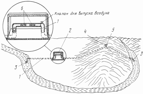
Hydroelectric contains conduit 1, passing through the open computer room 2. The ends of conduit with shut-off valves 3 are omitted in the river water at different levels. At the very top of the culvert is the filler neck 4 with a sealed lid 5, in the engine room are located within the conduit hydroelectric 6.
Hydroelectric power station works as follows
Airtight shut-off valves 3, 4 through the pipe conduit is completely filled with water, sealed nozzle cap 5, opening valves 3 and conduit begins to work as a siphon, ie through conduit flowing water, taken from the upper level to the lower level of the river. Due to the fact that the difference of level of the river by its flow is relatively stable, then once the work started in the siphon will pass through a water, resulting in hydraulic units work with a stable speed and force. Due to the fact that the transmission rate and the water pressure in the trap throughout its length the same, the machine room or more computer rooms with hydraulic units can be constructed on any section of passage of the siphon, for example, from the upstream to the lower layer, depending on the environmental eg away from the state reserves, where spawning fish, the climate, such as the distance from the shore of the river on a hill, which is not flooded floodwater spring, demographic, such as near cities to reduce energy loss in the transmission lines, and other objective conditions prevailing in the region. Since nature does not exist river with perfectly straight track, it makes economic sense to lay a siphon (water line) to the top level of the river in the lower level for a relatively straight line, by land, the level of which may greatly exceed the level of the source of the river. For example, if pave the siphon in a straight line from Penza, where the Qur'an proceeds to Saratov, where flows the Volga, or to make a trap between Abu-Hamed and Wadi Halfa, which are located on the Nile, you can get large (pressure) level difference in the siphon , spending much less kilometers of water pipeline (siphon), than to lay him on the bed, or the slope of the river valley.
From the above it is clear that the water line is a single trap, computer room or several computer rooms fashionable to build in any part of the passage of the siphon filler neck with a cover located at the very top of the trap and do not necessarily it must be located in the engine room, such as when computer room located in the village on the valley and the siphon routed through the hill or a mountain pass.
CLAIM
DAM Hydro power plants, including water pipeline passing through the machine shaft and coupled to the input and output sections of a watercourse, and hydraulic units, located on the main water pipe, characterized in that the conduit is designed as a siphon provided with a filler neck with a cover, with hydraulic units are located inside the siphon within turbine hall, the filler neck with a cover located in the upper part of the siphon and the input and output areas are equipped with a siphon and shut-off valves are located at different levels in the watercourse.
print version
Publication date 12.01.2007gg
![]()

Comments
Commenting, keep in mind that the content and the tone of your messages can hurt the feelings of real people, show respect and tolerance to his interlocutors, even if you do not share their opinion, your behavior in terms of freedom of speech and anonymity offered by the Internet, is changing not only virtual, but real world. All comments are hidden from the index, spam control.