1 shows a fluid power converter (general view);

2 shows a node and changing the orientation of the blade fixing position (first embodiment);

Figure 3 - view A-A in Figure 2;

4 - node changes the orientation and fixation of the blade position (the second option);

Figure 5 - node changes the orientation and fixation of the blade position (the third option);

Figure 6 shows a conical vane (side view);

7 illustrates a centrifugal speed controller power converter;

8 illustrates energy transducer mounted in the stream of water (river);

Figure 9 shows the position of trolleys in a circular path;

Figure 10 - view AA of the retaining strap assembly to change the orientation and fixation of the blade position;

11 - view of B-B of Figure 10;

Figure 12 - view of the drum of Figure 5;

13 - view of A-A of Figure 12;

Figure 14 - view of the inclined groove in the left drum;

Figure 15 - view of an inclined slot in the right drum;

On fig.16-17 shows the position (orientation) of the magnets of the left blade halves (N L -S L) and trolley (N -S inc) at points of orientation changes before and after the shift (dot-dashed line);

At 18-19 shows the position (orientation) of the magnets right blade halves (N L -S L) and trolley (N -S inc) at points of orientation changes before and after the shift (dot-dashed line);

Figure 20 shows the combined (hybrid) power vetrogidropreobrazovatel;

Figure 21 shows the assembly to change the orientation and fixation of the blade position (the fourth option);

Figure 22 - A view on the 21;

Figure 23 - view B-B by 21;

Figure 24 shows the construction of the head-limiting lever;

Figure 25 shows the limit stop;

Figure 26 shows the construction of the lifting mechanism and the extension of restrictive finger;

Figure 27 shows a section of the clutch disc;

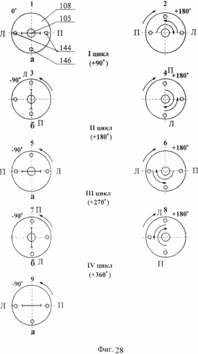
Figure 28 shows the disk clutch position after each cycle;

Figure 29 shows the assembly to change the orientation and fixation of the blade position at 22 (fifth embodiment);

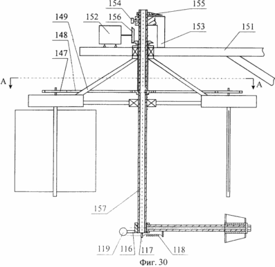
Figure 30 shows the energy transducer (underwater version);
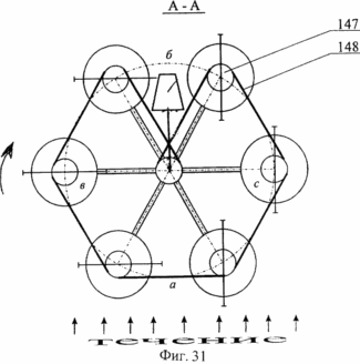
Figure 31 - view A-A in Figure 30 (a kinematic connection between the asterisks platforms);

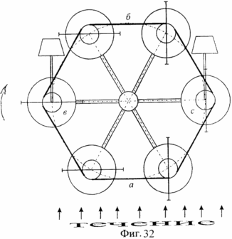
Figure 32 illustrates the kinematic connection between the sprockets platforms when the conical shaped wind vane mounted on two diametrically opposite platforms;
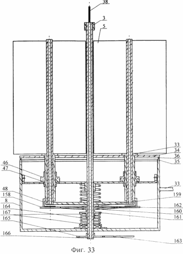
Figure 33 - node changes the orientation and fixation of the blade position (sixth embodiment);

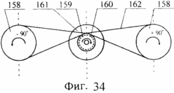
34 is - the kinematic connection between the internal and poluzvezdochkami asterisks;

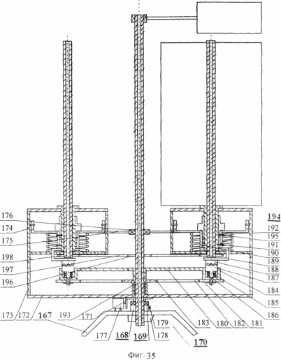
Figure 35 - node changes the orientation and fixation of the blade position;

Figure 36 shows the connection between the chain sprockets.

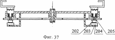
Figure 37 shows the rocker with dual tips;

Figure 38 shows a rocker structure (second embodiment) with single-tipped;

Figure 39 - 37 is a top view on;

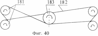
Figure 40 illustrates the kinematic connection between the first central sprocket and the four sprockets via the first chain 39 is on;

Figure 41 - the connection of the first central sprocket connection with two stars by the first circuit via the rocker 38 is on;
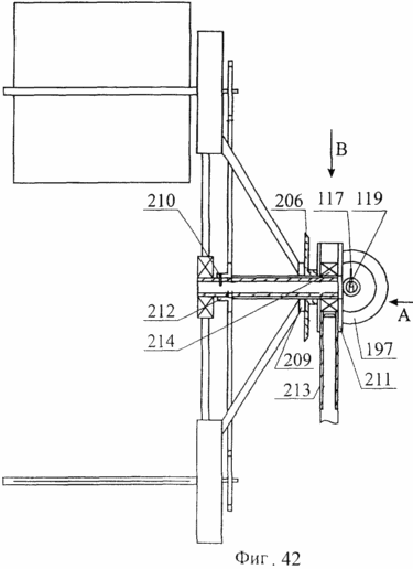
In Fig.42 - energy converter with platforms, rotating in a vertical plane;

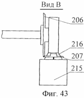
In Figure 43 - The view on Figure 42;

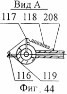
44 is - form A on Figure 42.

fluid energy converter comprising:

  • 1 circular road,

  • rotating platform (truck) 2,

  • weathervanes rack 3,

  • direction indicator (weathervane) 4,

  • flat blade 5,

  • direction indicator lever (weathervane) 6

  • Node 7 changes the locking position and orientation of the blades 5,

  • Platform body (trolley) 8,

  • flange 9

  • a mounting sleeve 10,

  • Platform cover 11,

  • thrust bearing 12,

  • bearing cap 13,

  • the cam disk 14,

  • cams 15,

  • Rollers 16,

  • the lower half coupling the coupling 17,

  • the upper half coupling the coupling 18,

  • finger 19,

  • vertical groove 20,

  • restrictive horizontal groove 21,

  • a first helical spring 22,

  • a first magnet 23 mounted on the blade 5,

  • a second magnet 24 mounted on the platform (trolley) 2;

  • saucer 25,

  • sleeve with a groove and a restrictive focus 26,

  • limiting finger 27,

  • rod 28,

  • spring 29,

  • rod 30,

  • blochok 31,

  • levers 32,

  • shaft 33,

  • rotating disk 34,

  • Platform cover 35,

  • rollers (balls) 36,

  • retaining bar 37,

  • the axis of rotation 38 of the two halves of the blade 5,

  • thrust bearing 39,

  • bushing 40 for installation of wind vane 4,

  • a second cylindrical spring 41,

  • the cam disk 42,

  • cams 43,

  • Rollers 44,

  • bushing 45 for mounting the blade halves 5,

  • the upper half coupling the coupling 46,

  • the lower half coupling the coupling 47,

  • Brackets 48

  • a magnet 49 mounted on the blade 5,

  • a magnet 50 mounted on the trolley 2,

  • bushing - thrust bearing 51,

  • third cylindrical spring 52,

  • post 53,

  • vertical groove 54,

  • Drum 55

  • inclined groove 56,

  • limiting finger 57,

  • limiting groove 58,

  • conical body 59 wind vane 4,

  • radial strut 60,

  • block 61,

  • rope 62

  • Jumper 63

  • tubular arm 64 wind vane 4,

  • sleeve 65,

  • a groove in the lever 66,

  • the rod 67,

  • centrifugal speed regulator 68,

  • drive 69,

  • slider with the slot 70,

  • finger 71,

  • vertical slot 72,

  • sleeves 73, 74,

  • ropes 75

  • Vertical and horizontal rods 76,

  • bevel gear pair 77,

  • the wheel 78

  • Bearing 79,

  • concrete block 80,

  • Resistant Front 81,

  • a sliding rack 82,

  • the thrust bearing 83,

  • Backup 84

  • the central shaft 85,

  • leading bevel gear 86,

  • a driven bevel gear 87,

  • a pair of bevel gears 88, 89, 90,

  • the rod 91,

  • sealed housing 92,

  • stand 93,

  • generator (pump) 94,

  • coupler 95,

  • AVB - active site,

  • Stops 96,

  • the first overrunning clutch 97,

  • second overrunning clutch 98,

  • first and second leading bevel gears 99, 100,

  • a driven gear 101,

  • level of the river (sea) 102,

  • generator (pump) 103

  • restrictive levers 104

  • the lever tip 105,

  • emphasis the restrictive 106,

  • the second spring 107,

  • clutch disc 108,

  • upper second coupling half the coupling 109,

  • the lower the coupling the second coupling half 110,

  • The pushing finger 111,

  • Bearing 112,

  • hub 113 for attaching the wind vane 5,

  • limiting groove 114,

  • Core 115

  • the first lever 116,

  • the second lever 117,

  • weather vane spring 118,

  • blochok 119,

  • glass of the first 120,

  • rod 121,

  • thrust lug 122,

  • wedge-shaped protrusion 123,

  • side lugs 124,

  • bolt fastening 125,

  • adjusting nut 126,

  • end protrusion 127,

  • finger-follower 128,

  • openings 129,

  • retractable finger 130,

  • a third spring 131,

  • Beads 132

  • Retractable rollers 133,

  • Bearing 134,

  • fourth spring 135,

  • the second glass 136,

  • rod 137,

  • button 138,

  • Latch 139

  • flat springs 140,

  • fifth spring 141,

  • Bearing 142,

  • finger-follower 143,

  • hole 144 (left) and (right)

  • slice wedge 145,

  • h - thickness of the clutch disc,

  • hole 146 for fixing the second spring 107,

  • star 147,

  • circuit 148,

  • backup 149,

  • the nut 150,

  • beam 151,

  • generator (pump) 152

  • Bracket 153

  • turn the lock 154,

  • pointer to the angle of rotation of wind vane 155,

  • bevel gear 156,

  • rod 157,

  • inner sprocket 158,

  • poluzvezdochku top 159,

  • poluzvezdochku bottom 160,

  • clutch disc 161,

  • the internal circuit 162,

  • 163 to an external circuit,

  • a second spring 164,

  • outer sprocket 165,

  • the axis of rotation of wind vane 166,

  • fixed rack 167,

  • mounting ring 168,

  • the thrust bearing 169,

  • leading gear 170,

  • driven gear 171,

  • horizontal fan-shaped supports 172,

  • Backup 173

  • platform 174 body

  • horizontal stops 175,

  • Bearing 176,

  • generator (or pump) 177,

  • pointer to the direction of flow of the medium 178,

  • lock the angular position of 179,

  • Rocker 180

  • first (lower) sprockets 181,

  • the first (bottom) circuit 182,

  • first central sprocket 183,

  • glass 184,

  • rod 185,

  • first spring 186,

  • a second lower coupling half the coupling 187,

  • a second upper coupling half the coupling 188,

  • Bracket 189,

  • cylinder with vertical and horizontal grooves 190,

  • the first guide pin 191,

  • the second guide pin 192,

  • a second central spring 193,

  • vertical groove 194,

  • horizontal groove 195,

  • the second central sprocket 196,

  • the second circuit 197,

  • the second (upper) sprockets 198,

  • rocker with dual tips 201,

  • upper magnets (N L -S L) 202

  • lower magnets (N toa -S) 203

  • lower rack 204

  • disc 205 of nonmagnetic material,

  • Rocker 199 with single lugs 200,

  • leading gear 206,

  • a driven gear 207,

  • the horizontal arm 208 of the conical weathervanes,

  • ring for attaching the struts 209,

  • Platform 210

  • the lever 211,

  • the central star 212,

  • rotating sleeve 213,

  • the thrust bearing 214,

  • generator 215,

  • generator 216 stand.