
|
Start of section
Production, amateur Radio amateurs Aircraft model, rocket-model Useful, entertaining |
Stealth Master
Electronics Physics Technologies Inventions |
Secrets of the cosmos
Secrets of the Earth Secrets of the Ocean Tricks Map of section |
  |
| Use of the site materials is allowed subject to the link (for websites - hyperlinks) | |||
Navigation: => |
Home / Patent catalog / Catalog section / Back / |
|
INVENTION
Patent of the Russian Federation RU2141718
![]()
METHOD OF INDUSTRIAL PRODUCTION OF ELECTRIC ENERGY
WITHOUT RATING OF RAW MATERIALS
The name of the inventor: Popkov Mikhail Ignatievich
The name of the patentee: Popkov Mikhail Ignatievich
Address for correspondence: 119136, Moscow, 3rd Setunsky Ave, 3, sq. 157, Popkov M.I.
Date of commencement of the patent: 1997.12.29
The invention - a method of industrial production of electric energy without the cost of raw materials - is one of the implementations of the "Monopulse effect" , according to which in any impulse of electric current (voltage) there is an unlimited supply of electricity, - "The energy of the electric pulse is inexhaustible". The method of industrial production of electrical energy without the cost of raw materials is that the coefficients of the expansion of periodic functions in the Inverse Fourier series determine the necessary composition of the harmonic amplitude spectrum for the synthesis of the periodic signal, synthesize, determine the parameters of the periodic signal, fix the presence of zones of excess potential in the synthesized periodic signal, Then the constant voltage of the external power source is selected from the average value of the periodic signal. The DC voltage is converted into a periodic pulse signal with a selected average voltage value, with a specified harmonic content of the amplitude spectrum, with fixed bands of the excess potential, and only then the voltages of a given harmonic composition of the amplitude spectrum with fixed bands of excess potential are filtered, each harmonic rectified, the rectified voltage of each harmonic Sum and the DC voltage obtained in this way is used as an electric power source for various consumers, the external power source is disconnected, then the work is transferred to the autonomous mode. In the special case, a pulse signal with a duty cycle of two different pulse shapes or video pulses of various shapes with an increased duty cycle and a uniform composition of the amplitude spectrum harmonics or radio pulses of various pulse shapes with an increased duty cycle and uniform harmonic composition in the immediate vicinity of the carrier frequency is used as a periodic signal. In a particular case, the DC voltage of the external power source is converted into two sinusoidal signals with different multiple frequencies, on the analog divider a pulse signal with a maximum coefficient equal to two for all harmonics of the amplitude spectrum of the received pulse signal is generated. The technical result is a reduction in the consumption of raw materials.
DESCRIPTION OF THE INVENTION
The invention - a method for the industrial production of electrical energy - is characterized by the fact that in order to exclude raw materials from production, electrical energy is converted by converting the DC voltage into electrical impulses containing harmonics that are filtered, the harmonics are rectified, summed and used for different consumers.
The proposed method is one of the implementations of the "Monopulse effect" [5] . The monopulse effect asserts that any impulse of an electric current (voltage) contains an unlimited supply of electrical energy. The energy of the electric pulse is inexhaustible.
The modern economy requires more and more energy for various consumers, and electricity plays a very important role here because of its universal qualities. Energy development is one of the most acute problems of today, which is given priority. The main drawback of modern electricity production is that electricity can be obtained only by using various types of raw materials, mainly organic fuels. Organic fuel (coal, oil, gas) occupies a dominant position in the fuel and energy balance of our country. Its share in the production of electricity accounts for more than 70%. At the same time, oil and gas reserves are constantly reduced, their production will cost more and more. Coal stations because of the uneven distribution of high-quality coal resources, its extraction and transportation will cost more and more.
The main obstacle to the use of solar power plants is the low intensity of solar radiation, which is 40,000 times less than in existing power converters. Therefore, in order to generate electricity of 1.0 million kW, an area of 100 km 2 is required , which additionally has an irreparable effect on the heat balance of the Earth.
In order to exclude the mutual influence of wind power stations, only 2-3 windmills can be placed on 1 km 2 of the area and a total power of 2.5 MW can be obtained. At the same time, the entire territory becomes a dead zone due to the infrasound noise created by the blades of the impellers. In addition, such electricity will be of poor quality due to the variability of wind speed.
Restrictions for tidal and geothermal power plants are obvious - binding to strictly defined areas of the Earth, where there are appropriate conditions for this (height of the amplitude of tides, availability of suitable sources of underground heat).
Hydroelectric power stations that convert the mechanical energy of the falling water flow into electricity by means of hydro turbines, which drive electric generators, lead to shallowing of rivers and flooding of fertile lands, which causes irreparable damage to the national economy.
At the core of nuclear power in its time was the principle "The energy of the atom is inexhaustible." This principle gave impetus to the development of various technical directions, which in their perfection are capable of destroying all life on the planet. Such a concept is harmful and therefore lifeless. In contrast to the atomic concept, another alternative concept is proposed: "The energy of the electric current pulse (voltage) is inexhaustible," which solves absolutely all the energy problems of our days and future.
So it is accepted, and it is reasonable that scientific ethics requires, before asserting that the predecessor was mistaken, to look for a mistake in oneself. In this case everything is checked and errors are excluded. Here is an elementary example:
1 + 1 = 2. (1)
The primary initial result is two. Scientific thought considered that such an equality is not suitable for higher mathematics and the value of two is too much. Therefore, the left and right sides of equality 1 are divided into two, that is,
1/2 + 1/2 = 1. (2)
It would seem that the arithmetic action here is not forbidden by mathematics and therefore both equalities are considered equivalent. However, all this is not so simple. Let's represent the left values of equalities - these are the coefficients determined by the amplitudes of the signals. Let us square both equations, we obtain in the first case
(1 + 1) 2 = 4 (3)
And in the second case
(1/2 + 1/2) 2 = 1. (4)
Consequently, as a result of dividing the left and right sides of the equation, its value decreases fourfold. In terms of signals, the signal power will be reduced fourfold or by the power level by -6.0 dB . This is an extremely large loss.
First-class scientists of the past did their best to prevent the first result and to direct the mathematical physics on the second result.
Leonard Euler (1707-1783) - a Swiss by birth, a philologist by education, lived for a long time in Russia, became a great mathematician, physicist, mechanic, astronomer - the main party to the dispute, together with D'Alembert and Lagrange on the possibility of decomposing a given function into a trigonometric The series introduced a formula bearing its name
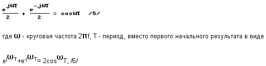
From which Euler's formula was obtained by dividing the left and right sides of equality 6. This gross error exists in mathematical physics for about 250 years since the middle of the 18th century. And dominates in the fundamental relationships of the fundamentals of the theory of spectra of radio engineering signals. Thus, the trigonometric Fourier series was defined by dividing the left and right sides of the original equality by two
![]()
Where a o , a n , b n are the Euler-Fourier coefficients, ![]() , T is the time, which led to the divergence of the series, since it reduces the amplitude of the original signal by a factor of two, or by a factor of four, or by the power level by -6.0 dB instead of the convergent Inverse Fourier series
, T is the time, which led to the divergence of the series, since it reduces the amplitude of the original signal by a factor of two, or by a factor of four, or by the power level by -6.0 dB instead of the convergent Inverse Fourier series
![]()
The well-known Dirichlet kernel
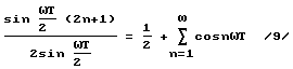
Is obtained by dividing the left and right parts of the following equality
Two, which led to disastrous consequences. Up to now, the Dirichlet integral, the Fourier integral, and many other formulas useful for practice exist with such an error.
In the materials of the application, attention is paid to a non-temporal process that has not been sufficiently studied yet, but to the amplitude spectrum of this process as an energy-based basis of the material world with an unlimited supply of electrical energy.
All of this has been studied in a sufficient degree for practical implementation. Thus, harmonic analysis and harmonic synthesis of spectral functions were introduced [1]. The phenomenon of the amplitude of a single spectral line is established [2]. As was shown above, the representation of pulse signals by the Fourier series leads to a decrease in the amplitude of the pulses by a factor of two, or by a factor of four, or by a power level of -6.0 dB [3]. In addition, the practical application of the Fourier integral reduces the amplitude of single pulses by a factor of 2n , or 39.48 times in power, or by 16.0 dB in power level [4]. It should be noted that in this situation the transition to the basic formulas of the theory of spectra of a new generation, for example 8, 10, is inevitable. This transition leads to the discovery of a previously unknown phenomenon that any voltage pulse (current) contains an unlimited supply of electrical energy, and the energy of any single pulse is inexhaustible [5].
According to the terminology adopted in radio engineering, the spectrum of any single pulse can be represented as a spectral density ![]() And the spectral density module
And the spectral density module ![]() . The spectral density of a single rectangular pulse is given by
. The spectral density of a single rectangular pulse is given by
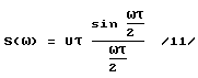
And gives the distribution is not the amplitude, as it should be, but the area of the pulse ![]() The product of the amplitude U by the frequency duration
The product of the amplitude U by the frequency duration ![]() . The absolute value or the spectral density module has a similar form
. The absolute value or the spectral density module has a similar form
Equal to half the value of the area of the pulse. Since the pulse width ![]() Determines the spectrum
Determines the spectrum ![]() And is a constant value, and only the amplitude of the pulse is subject to change, it can be confidently asserted that the spectral density 11 represents a rectangular pulse with a half value of the amplitude
And is a constant value, and only the amplitude of the pulse is subject to change, it can be confidently asserted that the spectral density 11 represents a rectangular pulse with a half value of the amplitude ![]() . Therefore, the amplitude spectrum of single pulses has not yet been determined. To find the amplitude spectrum of a single pulse of a rectangular shape, we take the integral of its spectral density in the form of equality
. Therefore, the amplitude spectrum of single pulses has not yet been determined. To find the amplitude spectrum of a single pulse of a rectangular shape, we take the integral of its spectral density in the form of equality
And therefore the amplitude spectrum of a single pulse of rectangular shape is twice as large as its spectral density.
Calculations with the amplitude spectrum of the pulse show that the integral of its value
It was shown above that by introducing an error in the Fourier series, the amplitude of all harmonics of the signal decomposition was doubled, or by a power level of -6.0 dB . This error is eliminated, and the amplitude of the harmonics of the spectrum is increased to its real value. And the spectrum of the periodic signal and the amplitude spectrum of a single pulse are equalized. Now the maximum coefficient of harmonics in the first and in the second case should not exceed two. The basis of the proposed method of industrial electric power production is the open "Monopulse effect" - the energy of any electric pulse is inexhaustible, therefore the proposed power plant will be called a single-pulse electric station ( MIPES ).
The set of actions aimed at the production of electricity, which characterizes the proposed method, includes the following methods.
- The choice of the DC voltage of the external power supply, which is the main parameter of the MIPES operation . The voltage value of such a source can be equal to 1, 10, 100, 200 V and any other voltage, depending on what power the station should work on. The design power of the external power source is selected as standard, equal to 1, 100, 10000, 40,000 VA, respectively, with a load of 1 ohm . The value of the voltage of the constant source determines the average value of the constant component of the periodic signal and its entire spectral composition. The greater the voltage of the external source, the greater the values of the harmonic components of the signal spectrum. In our case, in all cases, the external power source is assumed equal to the voltage of 100 V. The constant component for the considered variants is expected to be equal to 100 V. The maximum voltage of the harmonics of the pulse signal must not exceed 200V .
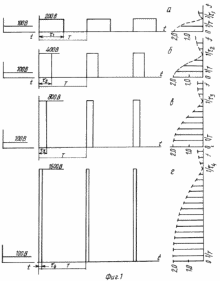
The selected voltage of the external power source is fed to a DC voltage converter into a pulse signal of a predetermined shape and a given amplitude spectrum with an infinite harmonic composition at the output of the converter. The pulse shape and the duty cycle are determined in advance - the ratio of the period to the pulse duration, the selection of which is shown in Fig. 1 . Here, a constant voltage of 100 V is converted into a square wave impulse signal with a maximum voltage of 200 V and a duty ratio of two shown in FIG. 1a , or a duty cycle equal to four, but the amplitude of the 400 V pulses (Figure 1b) or the amplitude in the 800 V pulse, but the duty cycle of eight ( Figure 1c ) or the pulse amplitude of 1600 V at duty cycle 16 (Figure 1d) - without any significant energy costs. In other words, as a result of converting a DC voltage of 100 V to an external power source with a power of 10000 VA, different harmonic composition of the amplitude spectrum can be obtained without additional energy costs. At the same 100 V , one harmonic can be obtained in the first fundamental lobe of the spectrum ( Figure 1a) , three harmonics ( Fig. 1b), seven harmonics ( Figure 1c ), 15 harmonics (Fig. 1d) , etc. to infinity . When the duty cycle of pulse signals increases, the pulse width decreases
 , The width of the fundamental lobe of the spectrum is increased, defined as 1 /
, Which leads to an increase in the number of harmonics in this part of the spectrum and at
, The width of the fundamental lobe of the spectrum is increased, defined as 1 /
, Which leads to an increase in the number of harmonics in this part of the spectrum and at  , And the number of harmonics and tends to infinity at a constant voltage of an external power source of 100 V.
- The selected voltage of the external power source is fed to a DC voltage converter into a pulse signal of a predetermined shape and a given amplitude spectrum with an infinite harmonic composition at the output of the converter. The pulse shape and the duty cycle are determined in advance - the ratio of the period to the pulse duration, the selection of which is shown in Fig.
1 . Here, a constant voltage of 100 V is converted into a square wave impulse signal with a maximum voltage of 200 V and a duty ratio of two shown in FIG.
1a , or a duty cycle equal to four, but the amplitude of the 400 V pulses (Figure 1b) or the amplitude in the 800 V pulse, but the duty cycle of eight (Figure 1c) or the pulse amplitude of 1600 V at duty cycle 16 (Figure 1d) - without any significant energy costs. In other words, as a result of converting a DC voltage of 100 V to an external power source with a power of 10000 VA, different harmonic composition of the amplitude spectrum can be obtained without additional energy costs. At the same 100 V , one harmonic can be obtained in the first fundamental lobe of the spectrum (Figure 1a) , three harmonics (Fig. 1b) , seven harmonics (Figure 1c) , 15 harmonics (Fig. 1d) , etc., to infinity . When the duty cycle of pulse signals increases, the pulse width decreases , The width of the fundamental lobe of the spectrum is increased, defined as 1 /
, Which leads to an increase in the number of harmonics in this part of the spectrum and at , And the number of harmonics and tends to infinity at a constant voltage of an external power source of 100 V.
- Filter each harmonic of the amplitude spectrum of a pulse signal obtained by converting the DC voltage of an external source into a pulsed signal by a separate filter.
- The signal of each harmonic, obtained by filtering the components of the pulse signal, is rectified, converting it into a constant voltage.
- Summarize the constant voltages, rectified signals of each harmonic on the total adder.
Depending on the DC voltage selected by the converter, the pulse in the pulse signal is determined by the gain in obtaining the output power of the MIPES and, consequently, the method of implementing this proposal is determined. Signals with a poor composition of harmonics can be designed for a low level of output power for the same material costs. But the implementation of such MIPES is distinguished by its accessibility and simplicity. Thus, a method for producing electric power is proposed, characterized in that, for the sake of simplest realization, the constant voltage of the external source is converted into a pulse signal with a duty ratio of two. Features of the implementation of the proposed method are shown in FIG. 1-1 . In Fig. 1-1a shows an approximate composition of the elements of the functional diagram, where K is the key that performs the function of transferring the MIPES to the autonomous operation mode. In this case, part of the DC voltage from the output of the adder C is fed to the station input instead of the external power supply voltage. P is a DC to pulsed signal converter with a duty cycle of two. Ф 1 , Ф 2 , ... Ф n - resonant high-Q filters, tuned to the 1st harmonic, 3rd harmonic, etc. Up to the 29th harmonic. В 1 , В 2 , ... In n - full-wave rectifiers, if possible with low losses. C is the total adder, possibly on the transformer, and H is the load of the consumers.
In Fig. 1-1b shows the pulse signal obtained at the output of the converter P.
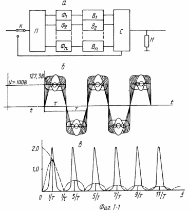 |
The peculiarity of the signal image in this form is caused by the fact that the true picture of impulses with harmonics that are present in this pulse and forms this pulse can not be recreated, due to the lack of measuring equipment. These impulses can only be synthesized. In Fig.
1-1b shows a synthesized pulse signal with a duty ratio of two and with all the harmonics that participate in its formation, from which it can be seen that in fact the harmonics of the spectrum form a constant zone, an excess potential zone - all that is greater than 100 V and a potential deficit zone, That is below 100 V.
The interaction of these zones leads to mutual compensation and the generation of pulses that are observed on the oscilloscope screen. In Fig.
1-1c shows the harmonics of the signal spectrum for this proposal and the filters tuned to these harmonics. Here we have the 1st harmonic with the resonance curve of the filter, the 3rd harmonic with the filter curve, etc. Up to the 29th harmonic. Calculated data on the power output of a power plant using a spectrum of pulses of the "Meander" type are given in Table.
1 . Here, for the 15 resonant filters, the data for calculating the harmonic coefficient 2A n , the harmonic coefficients obtained, 2A In , the alternating voltage of the harmonics at the output of the filters - U n , the expected sum of the DC voltage from the output of the rectifiers |
It can be seen from the calculation that if the impulse signal with a duty cycle of two and 15 resonant filters is used, the expected maximum power will be 88452.7 VA at a resistance of 1 ohms at a consumed power of an external power source of 10,000 VA . The gain is estimated not more than 78452.7 VA . The exact gain in obtaining a useful output power taking into account losses in the converter, filters, rectifiers and other non-specified factors can be evaluated when designing a specific device. But even at this stage of the review, the increase in power at the output of the adders to compensate for losses can be envisaged by increasing the number of filters, since the energy of any electric pulse is inexhaustible, and by increasing the DC voltage of the external power source, knowing that when the voltage of the power supply is doubled, 200 V power increases four times - 40,000 VA . The total voltage at the input of the adder will be 594.82 V , the capacity of the power plant will increase fourfold and amount to 353810.83 VA . The power gain here is 313810.83 VA , which solves all the problems associated with losses.
The second feature of the solution of the task in hand consists in actions characterizing the techniques when the voltage of the external power source is converted into frequency-determining repetition signals and forms a pulse signal with an increased duty cycle and any form of pulses. The change in the duty cycle of the pulse signals and the amplitude spectrum corresponding to these changes is characterized by an increased content of harmonics and gives a significant gain to the output power of the MIPES with the same number of resonance filters and the same voltage of the external source. What changes in the signal and its amplitude spectrum occur for the square wave and the duty cycle, 2, 4, 8 and 16 , is shown in Fig. 1 and discussed in detail above. The results shown apply to all other forms of video pulses. In Fig. 2 shows an exemplary functional diagram and pulse signals with amplitude spectra of a rectangular, triangular and cosine-biquadratic form with an increased duty cycle. The circuit shown in Fig. 2a contains the SG-master oscillator, FI-generator of various forms of video pulses. Φ n , B n , C, and H are the elements of the device according to the scheme of Fig. 1-1 , the difference is in the increased electrical strength. In Fig. 2b shows a pulse signal, which is obtained by converting a DC voltage of 100 V. In this case, the amplitude of the video pulse increases to 300 V with a corresponding change in the spectrum. In Fig. 2b, the same transformation steps lead to a triangular video pulse, but the amplitude of this pulse rises to 600 V. The amplitude spectrum of such a pulse signal is characterized by a large content of harmonics. |
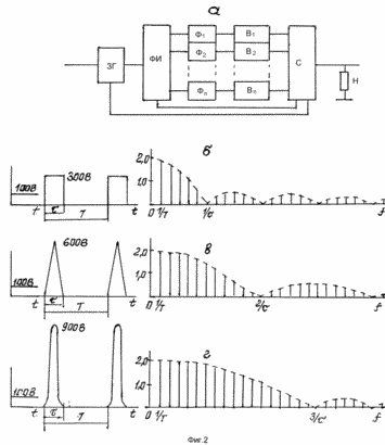 |
In this case, trapezoidal, cosine, cosine-wave, cosine-coded video pulses can be used, the number of harmonics in which, in the main lobe of the spectrum, takes an intermediate value between the rectangular and triangular pulses, and are of no particular interest. A more rich spectrum is possessed by cosine-biquadratic, cosine-like, etc. Video pulses by the content of harmonics in the main first-petal spectrum. In Fig.
2d shows the spectrum and cosine-biquadratic pulses after converting the DC voltage of an external source into a pulsed signal. In this case, the amplitude of video pulses increases to 900 V , and the number of harmonics here reaches 17 . This is significantly more than all of the above. For comparison, we give the power calculation data for 15 station filters. Calculated data on the output power of a power plant using a spectrum of video pulses of rectangular shape are given in Table.
2 , which shows the results for 15 resonance filters Φ n , the data X - in degrees, the values of sinX , the data X in radians, A n - the coefficients of the harmonics of the spectrum, U n - the variable component of the harmonic voltage at the output of the filters, ![]() U n - the sum of the DC voltage of the harmonics at the output of the rectifiers, (
U n - the sum of the DC voltage of the harmonics at the output of the rectifiers, (
![]() U n ) 2 - the expected total power received at the output of the adder BA . The calculation shows that when using a rectangular video pulse with an increased duty cycle and 15 resonant filters, a maximum power of 3188510.2 VA is expected at a resistance of 1 Ohm at an external power consumption of 10,000 VA . The gain can be estimated no more than 3178510.2 VA .
U n ) 2 - the expected total power received at the output of the adder BA . The calculation shows that when using a rectangular video pulse with an increased duty cycle and 15 resonant filters, a maximum power of 3188510.2 VA is expected at a resistance of 1 Ohm at an external power consumption of 10,000 VA . The gain can be estimated no more than 3178510.2 VA .
Calculated data of the output power of the power plant when using a spectrum of video pulses of triangular shape are given in Table.
3 . Here, Ф n - resonance filters, 2А n - coefficients of harmonics of the spectrum, U n alternating voltage of harmonics at the output of filters, ![]() U n is the expected sum of the DC voltage of the harmonics from the output of the rectifiers and (
U n is the expected sum of the DC voltage of the harmonics from the output of the rectifiers and (
![]() U n ) 2 - the expected total power at the output of the adder of the VA station. It can be seen from the above calculation that a triangular video pulse with the same duty cycle and constant voltage of an external source increases the output power of the station to 6899132.6 VA, which is 3710622.4 VA more than a rectangular video pulse produces under all equal conditions. The power gain on the station totalizer is estimated at 6889132.6 VA with a 1-ohm load when using a triangular video pulse.
U n ) 2 - the expected total power at the output of the adder of the VA station. It can be seen from the above calculation that a triangular video pulse with the same duty cycle and constant voltage of an external source increases the output power of the station to 6899132.6 VA, which is 3710622.4 VA more than a rectangular video pulse produces under all equal conditions. The power gain on the station totalizer is estimated at 6889132.6 VA with a 1-ohm load when using a triangular video pulse.
Calculated data on the power output of a power plant using the spectrum of a cosine-square-wave video pulse are given in Table.
4 , where for the resonant filters Φ n the data of the harmonics coefficients 2A n , U n - the harmonics voltage at the output of the filters, ![]() U n - total voltage from rectifier outputs, (
U n - total voltage from rectifier outputs, (
![]() U n ) 2 is the output power of the adder of the VA station. The value of the power that the power station can give at this type of pulse will be 8407796.1 VA . This is more for 1508663.5 VA triangular video pulse and for 5219285.9 VA more video pulse of a rectangular shape under all equal conditions. The power gain is estimated at 8397796.1 VA at 1 Ohm load .
U n ) 2 is the output power of the adder of the VA station. The value of the power that the power station can give at this type of pulse will be 8407796.1 VA . This is more for 1508663.5 VA triangular video pulse and for 5219285.9 VA more video pulse of a rectangular shape under all equal conditions. The power gain is estimated at 8397796.1 VA at 1 Ohm load .
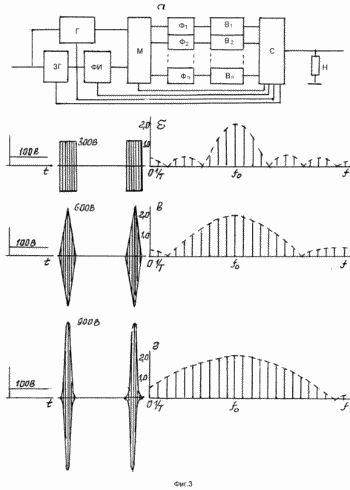 |
The third feature of the solution of the proposed method is associated with a further increase in the output power of MIPES when using an external power source with a voltage of 100 V , a power of 10,000 VA and 15 resonant filters. In addition to changes in the duty cycle and the shape of the video pulses for the increased power of the power plant, the transition to radio pulses under the same equal conditions can be used. In radio pulses, the amplitude spectrum is characterized by a greater uniformity of the harmonic amplitudes concentrated near the carrier frequency f o . The explanations of this proposal are shown in Fig. 3 . In Fig. 3a shows a functional diagram of a device in which a DC voltage of an external power source of 100 V is converted into a carrier signal f o and together with the generated signals after the MF and the PI is applied to a modulator M at the output of which a radio pulse signal with an increased duty cycle and various forms of radio pulses is received. In Fig. 3b shows radio pulses of a rectangular shape and the corresponding amplitude spectrum. The spectrum of such a radio pulse is symmetric with respect to the frequency f o , and to calculate the total amplitude, let's take the sum of the seven harmonics to the left of f o 1231.38 V , add the harmonic amplitude at a frequency f o 200 V and add it with the amplitudes of the seven harmonics to the right of f o 1231.48 V . The total voltage in this case will be equal to 2661.96 V. The expected maximum power will be as a square of the voltage and will be (2661.96) 2 , and equal to 7086031.0 VA . This is 3897520.8 VA more than for a rectangular video pulse under all equal conditions. The power gain when using a rectangular radio pulse under equal conditions will be 7076031.0 VA at a load of 1 Ohm . |
In Fig. 3c give the diagrams of the triangular radio pulse and its amplitude spectrum. To calculate the total amplitude, the seven harmonics to the left of f o will be 1354.8 V , plus 200 V center harmonic and 1354.8 V to the right of f o , which is 2909.6 V. The expected power on the adder will be 8465772.1 VA . This is 1566639.5 VA more than using a triangular video pulse. The power gain is defined as 8455772.1 VA at 1 Ohm load .
In Fig. 3d represent the cosine-biquadratic radio pulses and the amplitude spectrum of this signal. The total voltage here is defined as 1387.46V + 200V + 1387.46V = 2974.92V . The expected output power of the power plant is 8850149,0 VA . The difference compared to the video pulse will be 442352.9 VA . The power gain is equal to 8840149,0 VA at a load of 1 Ohm. Consequently, the transition from video pulses to radio pulses significantly increases the power of MIPES under all equal conditions .
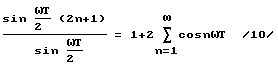
It is not difficult to see that in the transition from a cosine-biquadratic video pulse to a cosine-square-wave radio pulse, the difference in obtaining the output power does not undergo significant changes and amounts to only 442352.9 VA . This circumstance indicates an approach to the limit above which the considered increase in power loses its meaning under all equal conditions. However, such a limit can be achieved, but with a different approach. Such an approach is the use not of the Dirichlet kernel, which underestimates the amplitudes of the harmonics by a factor of two, but by an expansion of 10. This expansion has the feature that the coefficients of all the harmonics entering into it from the first to infinity are equal to two. In Fig. 4, an explanation is given of obtaining the limiting power when using the amplitude spectrum of pulse signals for industrial power generation. In Fig. 4a shows the functional diagram of the device according to this proposal. The constant voltage of the external source under these conditions is 100 V and 10000 VA is applied to two sinusoidal signal generators. One generator generates a continuous low-frequency sinusoid f / 2 equal to half the pulse repetition rate, and the second generates a high-frequency sfu2 / 2 (2n + 1) . These two signals are fed to the analog divider AD . The signals obtained at the output of the AD are filtered by F n , rectified with B n and summed on the adder C. FIG. 4b shows the signal and its amplitude spectrum, consisting of three harmonics with a voltage of 200 V each. The amplitude of the pulses here is 600 V. |
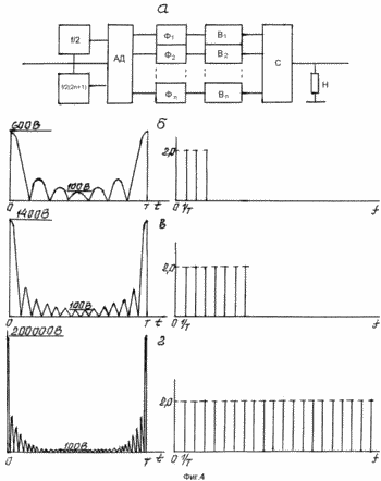 |
In Fig. 4c shows the signal at the output of the AD , containing seven harmonics of 200 V each . The amplitude of the signal increases to 1400 V. If we imagine a signal containing 15 harmonics, then its amplitude should increase to 3000 V. On 15 resonant filters, the total voltage will be of the order of 3000 V. And the power on the adder will acquire the ultimate value of 900,000 VA . In Fig. 4d an approximate depiction of the pulse signal and its amplitude spectrum for obtaining the limiting value of the output power. With 1000 resonant filters, the total voltage on the adder is 200,000 V. The output power of the adder can be expected - 40000000000 VA at a load of 1 ohm . This is more than 40 times the capacity of the Volkhov Hydroelectric Power Plant and the Dnieper Hydroelectric Power Plant, combined. If the voltage of the external source is increased to 200 V , the power plant capacity will increase (400,000) 2 to 160000000000 VA , and at 400 V (800,000) 2 - up to 60000000000 VA , which will provide the whole of Russia with electric power without the cost of raw materials and with compliance with environmental standards.
The proposed method can give good results not only at a high power level. And it is possible to build systems on the power measured by watts, milliwatts, etc. Here the possibilities have no limitations.
Thus, the amplitude spectrum of any voltage (current) pulse is an inexhaustible source of electrical energy that can be used for industrial purposes.
BIBLIOGRAPHY
MI Popkov. "Direct Fourier series", BNTE RI im. A.S. Popova, XIX Scientific Session, Moscow, 1963, p. 6-7.
M.I. Popkov. "Spectral effect", BNTO REE im. A.S. Popova, XIX Scientific Session, Moscow, 1963, p. 7-8.
MI Popkov. "Divergence of the Fourier series", "Radio engineering" N 5107 from 01.10.96 (in press).
M.I. Popkov. "Divergence of the Fourier integral", "Radio engineering" N 5247 from 13.05.97 (in press).
MI Popkov. "Monopulse effect", "Radio engineering" N 5279 dated July 3, 1997 (in press).
CLAIM
The method of industrial production of electric energy without the cost of raw materials, consisting in the fact that the coefficients of the expansion of periodic functions in the Inverse Fourier series determine the necessary composition of the harmonics of the amplitude spectrum for the synthesis of the periodic signal, synthesize, determine the parameters of the periodic signal, fix the presence of zones of excess potential in the synthesized periodic signal , после этого выбирают по усредненному значению периодического сигнала постоянное напряжение внешнего источника питания, при этом постоянное напряжение преобразуют в периодический импульсный сигнал с выбранным усредненным значением напряжения, с заданным составом гармоник амплитудного спектра, с фиксированными зонами избыточного потенциала и лишь тогда напряжения заданного состава гармоник амплитудного спектра с фиксированными зонами избыточного потенциала фильтруют, каждую гармонику выпрямляют, выпрямленное напряжение каждой гармоники суммируют и полученное таким путем постоянное напряжение используют в качестве источника электроэнергии для различных потребителей, после переводят работу в автономный режим.
Способ по п.1, отличающийся тем, что постоянное напряжение внешнего источника питания подают на преобразователь постоянного напряжения в импульсный сигнал, формируют импульсный сигнал со скважностью два различных форм импульсов, каждую гармонику амплитудного спектра импульсного сигнала со скважностью два фильтруют, напряжения гармоник выпрямляют, выпрямленные напряжения гармоник суммируют, с выхода общего сумматора полученное постоянное напряжение используют для различных потребителей электроэнергии и переводят работу в автономный режим.
Способ по п.1, отличающийся тем, что постоянное напряжение внешнего источника питания преобразуют в сигнал, задающий частоту повторения импульсов, формируют видеоимпульсы различных форм с повышенной скважностью и равномерным составом гармоник амплитудного спектра, каждую гармонику амплитудного спектра с равномерным составом фильтруют, напряжения гармоник выпрямляют, выпрямленные напряжения гармоник суммируют, с выхода общего сумматора полученное постоянное напряжение используют для различных потребителей электроэнергии и переводят работу в автономный режим.
Способ по п.1, отличающийся тем, что постоянное напряжение внешнего источника питания преобразуют в сигнал несущей частоты, формируют с помощью модулятора радиоимпульсы различных форм импульсов с повышенной скважностью и равномерным составом гармоник в непосредственной близости от несущей частоты, каждую гармонику амплитудного спектра радиоимпульсов с равномерным спектром вблизи несущей частоты фильтруют, напряжения гармоник выпрямляют, выпрямленные напряжения гармоник суммируют, с выхода общего сумматора полученное постоянное напряжение используют для различных потребителей электроэнергии и переводят работу в автономный режим.
Способ по п.1, отличающийся тем, что постоянное напряжение внешнего источника питания преобразуют в два синусоидальных сигнала с разными кратными частотами, на аналоговом делителе формируют импульсный сигнал с максимальным коэффициентом, равным двум для всех гармоник амплитудного спектра полученного импульсного сигнала, каждую гармонику амплитудного спектра с максимальным коэффициентом фильтруют, напряжения гармоник выпрямляют, выпрямленные напряжения гармоник суммируют, с выхода общего сумматора полученное постоянное напряжение используют для различных потребителей электроэнергии и переводят работу в автономный режим.
print version
Дата публикации 15.11.2006гг
![]()

Comments
When commenting on, remember that the content and tone of your message can hurt the feelings of real people, show respect and tolerance to your interlocutors even if you do not share their opinion, your behavior in the conditions of freedom of expression and anonymity provided by the Internet, changes Not only virtual, but also the real world. All comments are hidden from the index, spam is controlled.