| Start of section
Production, amateur Radio amateurs Aircraft model, rocket-model Useful, entertaining |
Stealth Master
Electronics Physics Technologies Inventions |
Secrets of the cosmos
Secrets of the Earth Secrets of the Ocean Tricks Map of section |
|
| Use of the site materials is allowed subject to the link (for websites - hyperlinks) | |||
Navigation: => |
Home / Patent catalog / Catalog section / Back / |
|
INVENTION
Patent of the Russian Federation RU2027278
![]()
THREE-PHASE COMPENSATOR OF REACTIVE POWER
The inventor's name: Klimash VS; Simonenko I.G.
The name of the patent holder: Komsomolsk-on-Amur Polytechnic Institute
Address for correspondence:
The effective date of the patent: 1992.04.30
Usage: for smooth adjustment of the amplitude and phase of the load voltage, providing full compensation of reactive power, stability of the output voltage and improving the symmetry of the three-phase load voltage system. SUMMARY OF THE INVENTION Three three-phase inverters with control systems are used in the control circuits of a three-phase transformer to control the phase of the inverter output voltages in each phase by the required angles ![]() At which the value of the output voltage and the value of the reactive power consumed remain at a given level, and single-phase voltage sensors and single-phase reactive current sensors are used, which together with inverter control systems provide automatic balancing of the three-phase output voltage system with the maximum power factor of the network.
At which the value of the output voltage and the value of the reactive power consumed remain at a given level, and single-phase voltage sensors and single-phase reactive current sensors are used, which together with inverter control systems provide automatic balancing of the three-phase output voltage system with the maximum power factor of the network.
DESCRIPTION OF THE INVENTION
The invention relates to electrical engineering, in particular to converter technology, and can be used to compensate for reactive power and improve the quality of electricity.
A device for improving the quality of electricity is known [1], which contains in each phase a single-phase booster transformer having one double primary winding with an average point and three secondary windings, two of which are made with a number of turns, two times less than the third, Each phase contains a single-phase controlled rectifier with a pulse-phase control system and a single-phase inverter with an inverter synchronized with the network. This device provides independent amplitude control in each phase, ensuring the stabilization of three-phase voltage at a given level with unbalanced load and unbalanced network.
However, the device does not provide phase balancing, which reduces the quality of electricity. In addition, it does not provide a reduction in the reactive power consumed from the network, but instead, with increasing control angles of the thyristors of the controlled rectifiers, consumes additional reactive power from each phase of the network, increasing the degree of phase asymmetry.
A three-phase reactive power compensator [2] is also known, comprising a three-phase controlled rectifier with a pulse-phase control system and a three-phase voltage inverter with a single-phase commutation and with a control system synchronized with the network, and a three-phase reactor connected between the network and the output of the inverter and a capacitor, Included in the DC link. In this device, the thyristors of the inverter are switched on so that the fundamental harmonic of its current is 90 ° higher than the mains voltage, thereby compensating for the reactive power of the network.
However, this reactive power compensator has limited capabilities and a low quality of the output voltage. It performs a partial compensation, depending on the capacity of the capacitor, which is also unregulated, since the controlled rectifier is disconnected and does not affect the amplitude of the compensation component of the network current. In addition, the device does not provide stabilization and balancing of the load voltage, which requires the use of additional AC voltage control devices in conjunction with it.
The known three-phase reactive power compensator, taken for the prototype [3], contains in each phase a single-phase rectifier, an LC filter, a single-phase inverter made on four valves, an inductive current controller made on two thyristors and two reactors, and contains in each phase The inverter control system synchronized with the circuit and the inductive current controller synchronized with the network, which are connected to the corresponding feedback sensors via the comparison elements.
Disadvantages of the device are limited functionality and low quality of power supplying the load. It does not ensure the stabilization and symmetry of the three-phase load voltage system and introduces large distortions into the shape of the current, especially when the angle of unlocking the thyristors of the inductive current controller varies from ![]() / 2 to
/ 2 to ![]() Radians in the process of regulating the generated reactive power.
Radians in the process of regulating the generated reactive power.
The purpose of the invention is to improve the quality of electric power by balancing the three-phase output voltage system in amplitude and phase.
The goal is achieved by adding three single-phase reactive current sensors, three single-phase voltage sensors, three single-phase current measuring transformers, a three-phase voltage measuring transformer and a three-phase transformer to the compensator, the secondary windings of which are connected in series with the primary windings of single-phase current transformers and are connected between the network and the load , And the primary phase windings are connected to the inputs of single-phase inverters, the secondary windings of single-phase current measuring transformers connected to the current inputs of single-phase reactive current sensors of the same name phases, whose voltage inputs are connected to the other two phases of the secondary winding of a three-phase voltage measuring transformer with a primary winding connected to the network , And the outputs of single-phase reactive current sensors are respectively connected to the first inputs of the inverter-controlled systems synchronized with the network, the inputs of the comparison elements through the voltage sensors are connected to load phases, and as a rectifier, a three-phase bridge rectifier connected by the input to the points of connection of the primary windings of single-phase measuring Current transformers and secondary phase windings of a three-phase transformer.
Such a device has the advantage that when the reactive power is compensated and the voltage is stabilized at a predetermined level, the three-phase load stress system is symmetric in each phase and the quality of the electric power is increased. In addition, the use of high-frequency pulse width modulation inverter improves the shape of the output voltage, which helps improve the quality of electricity. Finally, the claimed device uses a three-phase rectifier instead of three single-phase rectifiers and the voltage regulation function is assigned to the inverter, which reduces the number of rectifier valves and does not require the use of inductive current regulators, thereby simplifying the compensator circuit. This increase in the quality of electricity is achieved through the automatic regulation of two parameters - the duty ratio ![]() And phase
And phase ![]() Voltage of single-phase inverters depending on the magnitude of the reactive current and the magnitude of the voltage in each phase.
Voltage of single-phase inverters depending on the magnitude of the reactive current and the magnitude of the voltage in each phase.
 |
 |
||
| |||
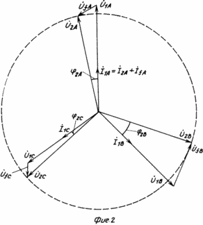
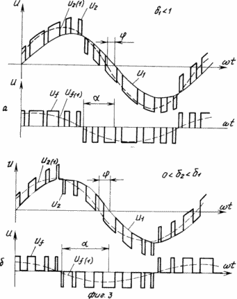
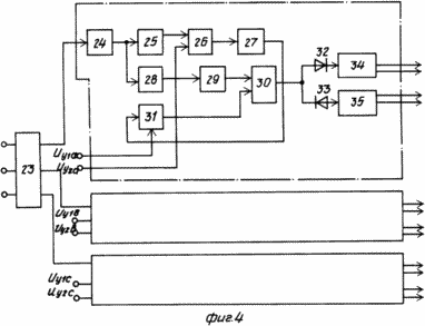
In Fig. 1 shows the circuit diagram of the power part of the reactive power compensator; In Fig. 2 - a vector diagram of the compensator; In Fig. 3 - time diagrams of inverter voltage and load for different values ![]() and
and ![]() ; In Fig. 4 is a block diagram of the inverter synchronized with the network to a level of known functional elements.
; In Fig. 4 is a block diagram of the inverter synchronized with the network to a level of known functional elements.
The compensator consists of a three-phase transformer 1, three single-phase inverters 2, 3, 4 with synchronized control systems 5, 6, 7, rectifier 8, single-phase current transformers 9, 10, 11, three-phase voltage measuring transformer 12, single-phase sensors 13, 14, 15 of the reactive current, the load voltage sensors 16, 17, 18, the comparison elements 20, 21, 22.
In the vector diagram of FIG. 2 U 1A , U 1B , U 1C - asymmetric three-phase system of network voltages, U 2A , U 2B , U 2C - symmetrical three-phase system of voltages on the load; U fA , U fB , U fC - voltage from the outputs of phase inverters A, B, C, respectively; I 1A , I 1B , I 1C - network currents in phases A, B, C, ![]() 2A ,
2A , ![]() 2B ,
2B , ![]() 2C - angles between voltage and load current of phases A, B, C, respectively.
2C - angles between voltage and load current of phases A, B, C, respectively.
In the timing diagrams of FIG. 3 U 1 - instantaneous value of the mains voltage, U 2 - instantaneous value of the voltage on the load and its first harmonic, U f , U f (1) - instantaneous value of the voltage of the inverter and its first harmonic, ![]() - the angle of regulation of the voltage of the inverter relative to the mains voltage,
- the angle of regulation of the voltage of the inverter relative to the mains voltage, ![]() - the angle between the voltage of the network and the load.
- the angle between the voltage of the network and the load.
The compensator works as follows.
The output voltage of the compensator, for example phase A, ![]() , Is formed from the mains voltage
, Is formed from the mains voltage ![]() And the voltage of a single-phase inverter 2, U fA
And the voltage of a single-phase inverter 2, U fA ![]() · L j
· L j ![]() , Regulated in amplitude by changing
, Regulated in amplitude by changing ![]() And in phase by changing
And in phase by changing ![]() . By means of the primary and secondary phase windings of the three-phase transformer 1, the output voltage of the single-phase inverter 2 is reduced by a factor of K m times and added to the mains voltage. As a result, the voltage of phase A of load 19 is
. By means of the primary and secondary phase windings of the three-phase transformer 1, the output voltage of the single-phase inverter 2 is reduced by a factor of K m times and added to the mains voltage. As a result, the voltage of phase A of load 19 is ![]()
It can be seen from expression (1) and from the vector diagram (Figure 2) that the amplitude and phase of the voltage vector ![]() Can be regulated by a change
Can be regulated by a change ![]() and
and ![]() . In the proposed compensator, the change in duty cycle
. In the proposed compensator, the change in duty cycle ![]() Is performed as a function of the deviation of the reactive current from zero, and the regulation
Is performed as a function of the deviation of the reactive current from zero, and the regulation ![]() - in the function of the deviation of the load voltage 19 from a given level. When the reactive power compensator consumes (generates) a signal from the output of a single-phase reactive current sensor 13 related to phase A under consideration enters the first control input synchronized with the network of the control system 5 of the single-phase inverter 2 and increases (decreases) the duty ratio
- in the function of the deviation of the load voltage 19 from a given level. When the reactive power compensator consumes (generates) a signal from the output of a single-phase reactive current sensor 13 related to phase A under consideration enters the first control input synchronized with the network of the control system 5 of the single-phase inverter 2 and increases (decreases) the duty ratio ![]() Due to high-frequency switching with a change in the duration of the conducting state of the valves of a single-phase inverter 2 according to the sinusoidal law (Figure 3), thereby increasing (decreasing) the angle between the voltage of the network
Due to high-frequency switching with a change in the duration of the conducting state of the valves of a single-phase inverter 2 according to the sinusoidal law (Figure 3), thereby increasing (decreasing) the angle between the voltage of the network ![]() And load voltage
And load voltage ![]() . In this case, a single-phase voltage sensor 16, by monitoring phase A voltage
. In this case, a single-phase voltage sensor 16, by monitoring phase A voltage ![]() , Provides a feedback signal to the comparison element 20, at which the signal is compared to a signal proportional to a predetermined value of the network voltage, for example, a nominal value. The difference of these signals from the output of the comparison element 20 is fed to the second control input of the single-phase inverter 2 synchronized with the network of the control system 5, changing the control angle
, Provides a feedback signal to the comparison element 20, at which the signal is compared to a signal proportional to a predetermined value of the network voltage, for example, a nominal value. The difference of these signals from the output of the comparison element 20 is fed to the second control input of the single-phase inverter 2 synchronized with the network of the control system 5, changing the control angle ![]() Valves of a single-phase inverter 2. As a result of such a targeted impact on
Valves of a single-phase inverter 2. As a result of such a targeted impact on ![]() and
and ![]() Voltage vector of single-phase inverter 2 2
Voltage vector of single-phase inverter 2 2 ![]() So forms its own module and the argument that the vector
So forms its own module and the argument that the vector ![]() Is the radius of the given circle.
Is the radius of the given circle.
The process of full compensation of reactive power with simultaneous stabilization of the voltage in the other two phases occurs analogously. This voltage regulation automatically ensures the balancing of the three-phase system of the output voltage.
In Fig. 4 23 - synchronizing transformer, 24 - synchronizer pulse generator, 25 - linear voltage generator, 26 - comparator, 27 - differentiator, 28 - frequency divider, 29 - triangular voltage generator, 30 - comparator, 31 - sinusoidal oscillator, 32, 33 - diodes, 34, 35 - output stages, U y1a , U y1b , U y1c - control signals from the reactive power sensors 13, 14, 15 connected to the phases A, B, C of the network, respectively, U y2a , U y2b , U y2c are the control signals coming from the voltage sensors 16, 17, 18 connected to the load phases A, B, C, respectively.
The use of the proposed reactive power compensator in comparison with the known ones makes it possible to fully compensate the reactive power of the load and to balance the output voltage independently of the external characteristic of the network, but also on the magnitude and nature of the load in the phases.
CLAIM
THREE-PHASE COMPENSATOR OF REACTIVE POWER, comprising in each phase a single-phase voltage inverter whose input is connected to the output of the rectifier and a synchronized with the network inverter control system with a second control input, characterized in that three single-phase reactive current sensors, three single-phase voltage sensors, Three single-phase current measuring transformers, three-phase voltage measuring transformer and three-phase transformer whose secondary windings are connected in series with the primary windings of single-phase current measuring transformers and are connected between the network and the load, and the primary phase windings of the three-phase transformer are connected to the outputs of single-phase inverters, Secondary windings of single-phase current measuring transformers are connected to the current inputs of single-phase reactive current sensors of the same name phases, whose voltage inputs are connected to the other two phases of the secondary winding of a three-phase voltage measuring transformer with a primary winding connected to the network, and the outputs of single-phase reactive current sensors respectively are connected to the first inputs Synchronized with the network of control systems of inverters, while inputs of the comparison elements through the voltage sensors are connected by an input to the phases of the load, and the output to the inverter control system, and as a rectifier a three-phase bridge rectifier connected by the input to the points of connection of primary windings of single-phase current measuring transformers and Secondary phase windings of a three-phase transformer.
print version
Published on February 15, 2007


Comments
When commenting on, remember that the content and tone of your message can hurt the feelings of real people, show respect and tolerance to your interlocutors even if you do not share their opinion, your behavior in the conditions of freedom of expression and anonymity provided by the Internet, changes Not only virtual, but also the real world. All comments are hidden from the index, spam is controlled.