

| section Home Production, Amateur Radio amateur Model aircraft, rocket- Useful, entertaining | Stealth master Electronics Physics Technologies invention | space Mystery Earth Mysteries Secrets of the Ocean Stealth section Map |   |
| Use of material is permitted for reference (for websites - hyperlinks) | |||
Navigation: => | Home / Products Patents / In the section of the catalog / back / |
|
INVENTION
Russian Federation Patent RU2157041
![]()
METHOD OF compensator voltage deviations
And reactive power
Name of the inventor: Klimash VS .; Simonenko IG
The name of the patentee: Klimash Vladimir Stepanovich; Simonenko Irina G.; Komsomolsk-on-Amur State Technical University
Address for correspondence: 681013, Komsomolsk-on-Amur, ul. Lenin 27, University of Technology, Patent Department
Starting date of the patent: 1998.11.25
The invention can be used in reactive power compensator having a channel input power factor correction and the output voltage. The technical result - reduction in the percentage of higher harmonic components in the output voltage. The method consists in the management of an inverter transformer-thyristor VAR compensator with a smooth amplitude-phase control voltage boost voltage. At low values of the amplitudes of the voltage boost voltage when the device provides virtually only stabilize the load voltage, a voltage inverter is operated by 180-degree algorithm, and in the region of large values, when required, and compensation of load voltage deviation and reactive power compensation deviations network, used 150 degree control algorithm. Translation inverter control from one algorithm to another is smoothly or discretely in dogranichnom inverter continuous current mode, voltage on one of the parameters that are directly or indirectly related to the inverter phase. It is proposed to make on the magnitude of the voltage at the input of the inverter.
DESCRIPTION OF THE INVENTION
The invention can be used in reactive power compensator having a smooth fast channel input power factor correction and the output voltage is made on the basis of the boost transformer and the thyristor converter with the amplitude and phase of the DC voltage intermediate link. SUMMARY OF THE INVENTION: voltage boost voltage rectifier formed by the filter and the inverter voltage booster transformers is regulated by the amplitude and phase so that the vector load voltage is a predetermined radius of the circle. At the same time in the low voltage boost voltage amplitude values that requires little or no compensation network reactive power and the device provides only a stabilization of the load voltage, a voltage inverter is operated by 180-degree algorithm, and in the high values that require compensation and load voltage deviation and reactive network capacity used 150 degree control algorithm. Translation voltage inverter control from one algorithm to another is smoothly or discretely in dogranichnom inverter continuous current mode, voltage on one of the parameters that are directly or indirectly related to the phase between current and voltage of the inverter, or the amplitude of the voltage boost voltage.
The technical effect of the method is double the percentage of reduction of the higher harmonic components in the output voltage of the curve.
The invention relates to power electronics and can be used in reactive power compensator for improving the quality of the output voltage.
Known method of controlling the deviation compensator voltage and reactive power (RF Patent N 2,056,692, 6 H 02 J 3/18, Bul. N 8, 1996), a three-phase booster transformer having a primary winding connected between the network and the load and the secondary winding is connected to star and through the three-phase voltage inverter, a filter and a reversible rectifier connected to the network or load, comprising the steps of measuring a deviation of the load voltage and therefrom generating a first control signal which, by acting on the three-phase inverter voltage change phase of the voltage at the output of inverter in the range 0 - ![]() I rad to the advance side relative to the supply voltage, while providing the length
I rad to the advance side relative to the supply voltage, while providing the length ![]() conducting state thyristor three-phase inverter voltage equal to
conducting state thyristor three-phase inverter voltage equal to ![]() rad (180-degree control), and a measured reactive power of the network and from the second control signal is formed which, acting on the reversible rectifier, changing the amplitude of the inverter output phase voltage, limited its minimum value, proportional to the predetermined range of voltage stabilization.
rad (180-degree control), and a measured reactive power of the network and from the second control signal is formed which, acting on the reversible rectifier, changing the amplitude of the inverter output phase voltage, limited its minimum value, proportional to the predetermined range of voltage stabilization.
The disadvantage of the prototype method should include a large percentage of the higher harmonic components in the output voltage curve at ![]() =
= ![]() in the high voltage boost voltage amplitude value when exercised and compensation of voltage variations and reactive power compensation. At the same time the use of a three-phase voltage inverter control algorithms
in the high voltage boost voltage amplitude value when exercised and compensation of voltage variations and reactive power compensation. At the same time the use of a three-phase voltage inverter control algorithms ![]() <
< ![]() happy to create a large surge due to occurrence of current-free intervals in the chain of secondary phase windings booster transformer when the device is a resistive load.
happy to create a large surge due to occurrence of current-free intervals in the chain of secondary phase windings booster transformer when the device is a resistive load.
The object of the invention is to improve the shape of the device without disrupting the output voltage of the inverter continuous current mode and the persistence of low switching losses.
The effect of solving this problem is two-fold decrease in the percentage of higher harmonic components in the output voltage of the curve.
The solution of this problem is achieved by measuring the voltage at the input of the three-phase inverter voltage, comparing it to a predetermined voltage level and above this level, correcting the first control signal, reducing the duration of the conducting state thyristor three-phase inverter voltage to 5 ![]() / Rad 6, wherein a predetermined voltage level at the input three-phase voltage inverter is chosen such that maintains the continuity of the current in the secondary phase windings of a three-phase booster transformer.
/ Rad 6, wherein a predetermined voltage level at the input three-phase voltage inverter is chosen such that maintains the continuity of the current in the secondary phase windings of a three-phase booster transformer.
The method includes measuring the compensator control operation voltage deviation across the load, it is formed of a first control signal, and measured and generating a second control signal and the reactive power of the network it. The first control signal changes phase in the range 0 - ![]() rad, and the second - the amplitude of the first harmonic voltage at the output of the three-phase voltage inverter with the limitation of its minimum value in proportion to a given range of stabilization. The three-phase voltage inverter converts the rectified input or output voltage compensator in the same AC frequency, but with amplitude and phase control depending on the first and second control signals. The voltage output from the three-phase inverter is supplied to the secondary windings of a three-phase booster transformer and decreasing them in time t k is added to the mains voltage. The method includes the operation and voltage measurement at the input of the three-phase voltage inverter, which alter the duration of the conducting state thyristor three-phase voltage inverter
rad, and the second - the amplitude of the first harmonic voltage at the output of the three-phase voltage inverter with the limitation of its minimum value in proportion to a given range of stabilization. The three-phase voltage inverter converts the rectified input or output voltage compensator in the same AC frequency, but with amplitude and phase control depending on the first and second control signals. The voltage output from the three-phase inverter is supplied to the secondary windings of a three-phase booster transformer and decreasing them in time t k is added to the mains voltage. The method includes the operation and voltage measurement at the input of the three-phase voltage inverter, which alter the duration of the conducting state thyristor three-phase voltage inverter ![]() 5
5 ![]() / 6 rad, above this voltage specified level, preserving the continuity of the current in the secondary phase windings of a three-phase booster transformer.
/ 6 rad, above this voltage specified level, preserving the continuity of the current in the secondary phase windings of a three-phase booster transformer.
A feature of the principle construction of the compensator is the relationship between the output current of the inverter phase and three-phase voltage magnitude at its input and output. This feature is the basis for a method of improving the quality of the output voltage of the compensator by switching the three-phase voltage inverter control algorithms without breaking the continuous current mode.
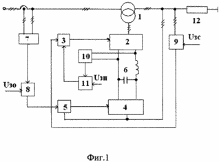 |  |
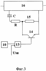 | 1 is a block diagram of an apparatus embodying the method of controlling the deviation compensator voltage and reactive power, Figure 2 - the timing diagrams modes compensator, and Figure 3 shows a functional diagram of an application switching device for changing the inverter control algorithm. Compensator (FIG. 1) comprises a three-phase booster transformer 1-phase inverter 2 voltage synchronized with the network system 3 controls, in which the formation of the first control signal, a reversible rectifier 4 with synchronized with the voltage at its input terminals the system control unit 5, in which the generating a second control signal, a capacitive-inductive filter 6. In addition, the sensor 7 comprises a compensator reactive power limiter network 8 undervoltage level sensor 9 deflection load voltage sensor 10 of the input voltage of three-phase voltage inverter, the switching device 11 and load 12. The structure of the switching device (4) includes a comparator 13, switch 14 (transistor) and an additional resistor 15 for the one-shot 16. |
The first control voltage input control system 3-phase inverter 2 is connected to the output of the sensor 9, the voltage deviation of the load 12, in which the phase is regulated boost voltage in the range 0 - ![]() glad the advance side supply voltage. The second control input of the control system 3 the three-phase voltage inverter 2 through the switching device 11 is connected to the sensor 10 input voltage three-phase inverter 2 at which the inverter switch control algorithms. The control input of the control system of reversible rectifier 4 through 5, the minimum voltage level limiter 8 connected to the output of the sensor 7, the network reactive power, the magnitude of which govern the amplitude of the additional stress.
glad the advance side supply voltage. The second control input of the control system 3 the three-phase voltage inverter 2 through the switching device 11 is connected to the sensor 10 input voltage three-phase inverter 2 at which the inverter switch control algorithms. The control input of the control system of reversible rectifier 4 through 5, the minimum voltage level limiter 8 connected to the output of the sensor 7, the network reactive power, the magnitude of which govern the amplitude of the additional stress.
Voltage deviation compensator and reactive power (FIG. 1) according to the proposed method is as follows.
For small values of the angle ![]() 12 load amplitude voltage boost voltage has a minimum value (Figure 2, B) defined by a predetermined range of voltage regulation, and is regulated only by a phase voltage deviation across the load 12 by a predetermined function, such as nominal level. The voltage at the input voltage three-phase inverter 2 below the inverter switching control algorithms 2 voltage and it works as in the prior art with a 180-degree control algorithm. By increasing the angle
12 load amplitude voltage boost voltage has a minimum value (Figure 2, B) defined by a predetermined range of voltage regulation, and is regulated only by a phase voltage deviation across the load 12 by a predetermined function, such as nominal level. The voltage at the input voltage three-phase inverter 2 below the inverter switching control algorithms 2 voltage and it works as in the prior art with a 180-degree control algorithm. By increasing the angle ![]() load 12 increases the signal output from the sensor 7 network reactive power. This causes an increase in the input voltage three-phase inverter 2 and their values are exceeded, causes a change in the load angle between the inverter
load 12 increases the signal output from the sensor 7 network reactive power. This causes an increase in the input voltage three-phase inverter 2 and their values are exceeded, causes a change in the load angle between the inverter ![]() / 12 to 11
/ 12 to 11 ![]() / 12 rad, changes the duration
/ 12 rad, changes the duration ![]() conducting state thyristor three-phase voltage inverter
conducting state thyristor three-phase voltage inverter ![]() 5
5 ![]() / 6 rad (Fig. 2a) via a switching device 11. The switching device 11 (FIG. 4) may be applied to comparator 13, which turns off the transistor 14, a shunt 15 series resistor monostable 16, the intended delay intervals for forming the conductive state thyristors on the recovery of their locking properties and the introduction of this additional resistance increases the length of the delay before
/ 6 rad (Fig. 2a) via a switching device 11. The switching device 11 (FIG. 4) may be applied to comparator 13, which turns off the transistor 14, a shunt 15 series resistor monostable 16, the intended delay intervals for forming the conductive state thyristors on the recovery of their locking properties and the introduction of this additional resistance increases the length of the delay before ![]() / 6 rad thereby reducing
/ 6 rad thereby reducing ![]() 5
5 ![]() / 6.
/ 6.
Apparatus (FIG. 1), realizing the proposed control method, provides an adjustable voltage magnitude and phase angle change of the rectifier control ![]() and in inverter
and in inverter ![]() and. The compensator change
and. The compensator change ![]() to be made in the deflection function of reactive power from the network level of zero, and the change of the angle
to be made in the deflection function of reactive power from the network level of zero, and the change of the angle ![]() and - load voltage deviation from a predetermined level functions. Such automatic control allows stabilization of the load voltage and reactive power compensation of the network independent of the stiffness characteristics of the external network, and also on the size and nature of the load.
and - load voltage deviation from a predetermined level functions. Such automatic control allows stabilization of the load voltage and reactive power compensation of the network independent of the stiffness characteristics of the external network, and also on the size and nature of the load.
Using the equalizer control method allows to improve the quality of supply of electricity consumers and reduce losses in power lines.
CLAIM
A method of controlling the compensator voltage deviations and reactive power, comprising a three-phase booster transformer with a primary winding connected between the network and the load and a secondary winding connected in star, and through the three-phase voltage inverter, a filter and a reversible rectifier connected to the network or load, comprising: measuring a voltage across the load and deflection thereof forming a first control signal which, acting on the inverter voltage phase, phase change voltage boost voltage in the range 0 - ![]() I rad to the advance side relative to the supply voltage, while providing the length of the conductive state of the thyristors of three-phase inverter voltage equal
I rad to the advance side relative to the supply voltage, while providing the length of the conductive state of the thyristors of three-phase inverter voltage equal ![]() rad, and and measured reactive power network and therefrom generating a second control signal which, by acting on the reversible rectifier, changing the amplitude of the voltage boost voltage limited at its minimum value determined by the predetermined range of voltage regulation, wherein the measured input voltage of three-phase voltage inverter , comparing it to a predetermined voltage level and above this level, correcting the first control signal, reducing the duration of the conducting state thyristor three-phase inverter voltage to 5
rad, and and measured reactive power network and therefrom generating a second control signal which, by acting on the reversible rectifier, changing the amplitude of the voltage boost voltage limited at its minimum value determined by the predetermined range of voltage regulation, wherein the measured input voltage of three-phase voltage inverter , comparing it to a predetermined voltage level and above this level, correcting the first control signal, reducing the duration of the conducting state thyristor three-phase inverter voltage to 5 ![]() / Rad 6, wherein a predetermined voltage level at the input three-phase voltage inverter is chosen such that maintains
/ Rad 6, wherein a predetermined voltage level at the input three-phase voltage inverter is chosen such that maintains
continuity of current in the secondary phase windings of a three-phase booster transformer.
print version
Publication date 15.02.2007gg
![]()


Comments
Commenting, keep in mind that the content and the tone of your messages can hurt the feelings of real people, show respect and tolerance to his interlocutors, even if you do not share their opinion, your behavior in terms of freedom of speech and anonymity offered by the Internet, is changing not only virtual, but real world. All comments are hidden from the index, spam control.