| Start of section
Production, amateur Radio amateurs Aircraft model, rocket-model Useful, entertaining |
Stealth Master
Electronics Physics Technologies Inventions |
Secrets of the cosmos
Secrets of the Earth Secrets of the Ocean Tricks Map of section |
|
| Use of the site materials is allowed subject to the link (for websites - hyperlinks) | |||
Navigation: => |
Home / Patent catalog / Catalog section / Back / |
|
INVENTION
Patent of the Russian Federation RU2006527
![]()
METHOD OF ELECTROLYSIS OF WATER AND INSTALLATION FOR ITS IMPLEMENTATION
The name of the inventor: Dudin VN; Samsonov N.M.
The name of the patent holder: Dudin Vasily Nikitich
Address for correspondence:
The effective date of the patent: 1991.03.29
The method consists in bringing the electrolyte to the electrodes, mixing the electrolyte in the interelectrode space, decomposing the water into oxygen and hydrogen under the action of a constant electric current and in removing the resulting gases. Stirring of the electrolyte in the interelectrode space is performed by pulsating the pressure of at least one of the gases produced during the electrolysis of the water. A device for electrolysis of water in which the device for stirring the electrolyte in the interelectrode space is made in the form of a membrane regulator with a spring provided with an additional spring hinged by one side to the stem of the membrane and the second side to the regulator body, the axis of the neutral position of the additional spring being perpendicular to the axis The main spring of the membrane regulator.
DESCRIPTION OF THE INVENTION
The invention relates to the field of electrolysis systems and can be used in installations for electrolysis of water operating in any position with respect to the gravity vector.
A method of electrolysis of water is used, which is used in industry to produce oxygen and hydrogen. The method includes the electrolyte supply to the electrodes, the decomposition of water into oxygen and hydrogen under the action of a constant electric current, the evacuation of the produced gases, the removal of heat from the electrolysis zone by circulation of the electrolyte, and mixing of the electrolyte in the interelectrode space.
The device for carrying out this method consists of an electrolytic cell, separation columns operating due to the difference in working medium densities, refrigerators, gas pressure regulators, circulation and feed pumps.
A disadvantage of the known method and device is the complexity and inability to use them in installations operating in any position with respect to the gravity vector.
The aim of the invention is to reduce the mass-dimension characteristics and increase the service life by eliminating the gas-liquid mixture separators from the unit and the continuously operating circulating pump.
This goal is achieved through the following technical solutions.
In contrast to the known method, the mixing of the electrolyte is not due to its circulation, but due to pressure pulsations of at least one of the gases.
By introducing a membrane controller in the installation circuit, which ensures the pulsation of the pressure of one of the gases.
 |
 |
 |
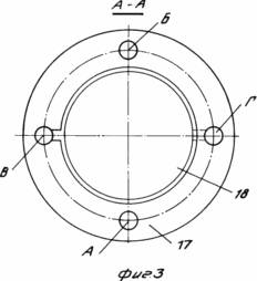
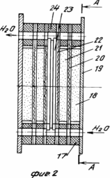
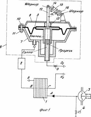
In Fig. 1 is a schematic diagram of an installation for carrying out the method according to the invention; In Fig. 2 - general view of cells of the cell electrolyzer; In Fig. 3 is a sectional view of AA in FIG. 2. | ||
The installation for carrying out the proposed method of electrolysis of water, operating in any position with respect to the gravity vector, consists of an electrolyzer 1, a buffer tank 2, a membrane tank 3, an electromagnetic valve 4, a throttle 5, a membrane controller 6 including: half-shells 7 and 8 , The diaphragm 9, the bolts 10, the nuts 11, the diaphragm stem 12, the spring 13, the stem 14, the spring 15 and the rod 16. The stem 14 is pivotally connected to the stem 12 of the diaphragm 9 and has, on the hinge side, an outer support band for the spring 15. The second side The rod 14 extends along the inward landing of the rod 16 hingedly connected to the regulator body 8 and having an outer support band for the opposite side of the spring 15.
Depending on the position of the membrane 9 and its stem 12, the distance between the bearing bands of the rods 14 and 16 for the spring 15 changes, which corresponds to a greater or less compression of the spring 15. The neutral position of the spring 15 is the position where the spring axis 15 is perpendicular to the axis of the rod 12 and the spring 13 .
On both sides of the axis of the neutral position of the spring 15, the force of this spring, multiplied by cos ![]() (See Figure 1), or is added to the force of the spring 13 (angle
(See Figure 1), or is added to the force of the spring 13 (angle ![]() > 90 o ), or subtracted from it (
> 90 o ), or subtracted from it ( ![]() <90 o ).
<90 o ).
The proposed installation operates using the proposed method as follows.
The initial state of the installation for carrying out the proposed method of electrolysis of water: the cell is turned off, the outlet through the nozzle of the membrane regulator is closed by a valve ( ![]() > 90 o ), the solenoid valve 4 is closed.
> 90 o ), the solenoid valve 4 is closed.
The overlapping of the slot of the nozzle by the diaphragm regulator valve is ensured by the force of the spring 13, which exceeds the force of the spring 15 by the required amount for any position of the membrane. 9. The electrolysis cell starts and the decomposition of water into oxygen and hydrogen begins. The pressure of the gas overlapped by the membrane regulator 6 begins to increase, which will result in certain pressures and ![]() (
( ![]() <90 о ) to the opening of the regulator valve 6 and the gas discharge from the unit through the throttle 5. The pressure relief will again shut off the nozzle slot of the regulator valve 6 (see Figure 1), and the cycle of increasing and falling pressure is repeated.
<90 о ) to the opening of the regulator valve 6 and the gas discharge from the unit through the throttle 5. The pressure relief will again shut off the nozzle slot of the regulator valve 6 (see Figure 1), and the cycle of increasing and falling pressure is repeated.
Such a pulsation of the pressure of the gas (oxygen and hydrogen) is determined by the operation of the regulator 6, having different values of the pressure difference on both sides of the membrane 9 ![]() P) to open and close the slot of the nozzle with a valve. Various
P) to open and close the slot of the nozzle with a valve. Various ![]() P opening and closing the slot of the nozzle by the valve are provided by the selection of the power characteristics of the springs 13 and 15 and their position relative to each other when it becomes possible at certain positions of the membrane 9 or the action of the forces of both springs in one direction
P opening and closing the slot of the nozzle by the valve are provided by the selection of the power characteristics of the springs 13 and 15 and their position relative to each other when it becomes possible at certain positions of the membrane 9 or the action of the forces of both springs in one direction ![]() > 90 о ), or their counteraction to one another (
> 90 о ), or their counteraction to one another ( ![]() <90 ° ) (see Figure 1). The purpose of the buffer tank 2 and the throttle 5 is to increase the cycle time of the gas pressure pulsation by reducing the rate of its increase and fall. The pulsation of the gas pressure (in accordance with Figure 1 of oxygen) causes migration of the electrolyte in the pores of the anode 18 and, respectively, in the diaphragm 20 and the porous cathode 21 (see Figure 2). This is because an increase in the oxygen pressure leads to an increase in the pressure difference between the oxygen and the electrolyte that is produced. The electrolyte pressure is maintained below atmospheric pressure by installing a spring in the membrane tank 3 (see Figure 1).
<90 ° ) (see Figure 1). The purpose of the buffer tank 2 and the throttle 5 is to increase the cycle time of the gas pressure pulsation by reducing the rate of its increase and fall. The pulsation of the gas pressure (in accordance with Figure 1 of oxygen) causes migration of the electrolyte in the pores of the anode 18 and, respectively, in the diaphragm 20 and the porous cathode 21 (see Figure 2). This is because an increase in the oxygen pressure leads to an increase in the pressure difference between the oxygen and the electrolyte that is produced. The electrolyte pressure is maintained below atmospheric pressure by installing a spring in the membrane tank 3 (see Figure 1).
Increasing the pressure difference between oxygen and electrolyte squeezes out the electrolyte from the anode pores of the appropriate size. Reduction of pressure difference, on the contrary, leads again to the filling of these pores with electrolyte. The release of pores from the electrolyte with increasing pressure drop and the filling of the same pores with electrolyte with decreasing pressure drop will occur in accordance with the well-known equation for determining the critical pressure drop according to the Barus-Buchholz method.
Thus, the ripple of the oxygen pressure results in a periodic (according to the oxygen pressure change cycle) movement of the electrolyte in the porous anode 18, the diaphragm 20, and the porous cathode 21. This reduces the concentration polarization of the electrolysis cell, increases the corrosion resistance of the electrodes, especially the anode (by increasing the electrolyte concentration At the anode), that is, leads to a certain decrease in voltage on the electrolysis cell and an increase in the life of the electrodes.
The introduction of an invention in the industry that provides a higher service life of the electrodes and a certain (by 20-50 mV) reduction in voltage on the electrolysis cell gives a noticeable economic effect. (56) Yakimenko AM et al. Electrolysis of water. M.: Chemistry, 1970, p. 180-186.
CLAIM
A method for electrolyzing water to produce oxygen and hydrogen, which comprises supplying water to the interelectrode space, mixing and withdrawing oxygen and hydrogen, characterized in that, in order to simplify the process, mixing is performed by pulsating the pressure of oxygen or hydrogen
2. An apparatus for electrolysis of water comprising an electrolytic cell with electrodes and porous hydrophilic diaphragms, oxygen and hydrogen outlet ports, an electrolyte circuit with a membrane vessel, and a mixing device, characterized in that, in order to simplify the process, the mixing device is designed as a membrane controller With a spring connected to an oxygen or hydrogen nozzle provided with an additional spring connected by one side with a hinge to the stem of the membrane and the other side to the regulator body, the neutral axis of the additional spring being perpendicular to the axis of the main spring of the membrane regulator.
3. The plant according to claim 2, characterized in that a buffer tank is located between the oxygen or hydrogen nozzle and the regulator, and the throttle is installed at the output of the regulator.
print version
Publication date 27.02.2007gg


Comments
When commenting on, remember that the content and tone of your message can hurt the feelings of real people, show respect and tolerance to your interlocutors even if you do not share their opinion, your behavior in the conditions of freedom of expression and anonymity provided by the Internet, changes Not only virtual, but also the real world. All comments are hidden from the index, spam is controlled.