| section Home
Production, Amateur Radio amateur Model aircraft, rocket- Useful, entertaining |
Stealth master
Electronics Physics Technologies invention |
space Mystery
Earth Mysteries Secrets of the Ocean Stealth section Map |
|
| Use of material is permitted for reference (for websites - hyperlinks) | |||
Navigation: => |
Home / Products Patents / In the section of the catalog / back / |
|
INVENTION
Russian Federation Patent RU2246784
![]()
Singlet oxygen generator in emerging THREADS
Name of the inventor: Safonov VS
The name of the patentee: Physics Institute. PN Lebedev, the Russian Academy of Sciences
Address for correspondence: 443011, Samara, ul. Novo-Sadovaya, 221, Samara Branch of the Physical Institute. PN Lebedev, the Russian Academy of Sciences
Starting date of the patent:
The invention relates to the chemical art and may be used in the development of chemical lasers. Singlet oxygen generator comprises a housing, injector chlorine-throttle valve and an injector solution. Each solution injector bore extends at least two strands arranged on the edges of the hole with a gap therebetween. The jet of solution emerges from the holes formed and further movement downward along the yarn surface and between them. When moving between the flow chlorine jets solution chlorination reaction occurs alkaline solution of hydrogen peroxide to form singlet oxygen and chlorine utilization. The filaments may extend from one hole parallel at an angle to each other, and a cross yarns or filaments from touching another hole injector solution. The presence in solution of the injector hole at least two filaments not only direct the jet but also to control the jet flow as desired shape and geometric characteristics of the jet by changing the relative position of the filaments in a jet. This makes possible the realization of different types of generators of singlet oxygen with increased reaction surface and the work efficiency, and is stable during jets between filaments increases the reliability of the device. Ensure the expansion of the technological capabilities of the generator application.
DESCRIPTION OF THE INVENTION
The invention relates to spray generators of singlet oxygen and can be used in the development of chemical lasers, and in chemical engineering.
Known ink-jet generator of singlet oxygen (SGSK) "continuous SGSK is a modification of the pulse SGSK colliding jets alkaline solution of hydrogen peroxide and chlorine." (M.V.Zagidullin, A.Yu.Kurov et al., "High-performance jet generator of O 2(1 ![]() ) "," Quantum Electronics ", 18, №7 (1991), p. 826).
) "," Quantum Electronics ", 18, №7 (1991), p. 826).
The same generator of singlet oxygen and its use in a chemical oxygen-iodine laser described in "Quantum Electronics", "CE" 18 №12 (1991), page 1417, "CE" 21 №1 (1994) page 23, "CE".. №2 (1994) p. 129 and others.
Is similar to "output SGSK structure with oxygen flow vertically upward through the central opening in the nozzle array through which alkaline solution of hydrogen peroxide is fed into the reactor." (M.V.Zagidullin, V.D.Nikolaev and others. "The supersonic oxygen-iodine laser power of 1.4 kW to gain a length of 5 cm and nitrogen dilution of the active medium." ( "Quantum Electronics", 30, №2 (2000 ), p. 161). This design is a dual generator with respect to the above, since the top of the generator at the edges there are two bars for injection of the alkaline solution of hydrogen peroxide composed of the injector body and tubes, between which there is a hole for exit of singlet oxygen. The injectors are located below the chlorine generator. The jet injector solution from the tubes gratings fed downward jet chlorine jets are injected perpendicularly solution further flow of chlorine is rotated 90 ° between the jets and the solution moves upward, i.e. countercurrent mode motion implemented solution and chlorine flow jets . This counter-jet generator of singlet oxygen.
Counter-motion of free jets and chlorine solution flow, the location of injection solution gratings at the top and bottom of the generator chlorine injectors, the injection of chlorine jets perpendicular to the jets of the solution - this property is common to all these constructions generators of singlet oxygen.
A jet having a diameter d = 0,3 ... 1 mm, and a length L> 100 mm, ie the ratio L / d> 100. With this jet against the initial portion of a few millimeters, the rest of the jet expands in a conical shape. At the same time continuously reduced cross-sectional area of the flow passage between the chlorine solution jets. In the final section of the jet due to the continuous expansion and internal stresses on the jet breaks the cone. jet breaking products and reduce the area for the passage of chlorine between the jets.
It was in this place in a counter-oscillator is used to enter chlorine jets with a maximum speed (injection) is perpendicular to the jets of the solution, since the sectional area for the passage of chlorine between the jets is minimal. Such chlorine input coupled with poor quality of the solution on the end part of the jets causes destruction ( "spraying") jets surface. Product damage in the form of splashes, droplets and aerosol generated singlet oxygen makes the generator to the resonator chemical oxygen-iodine laser. The presence of the aerosol solution in the cavity leads to scattering of laser radiation on the particles of the aerosol, which reduces the power of the laser radiation. Release of drops of solution into the cavity leads to splashing mirrors and emergency mode laser. To avoid entrainment of the counter generator is necessary to increase the speed of the solution jets or reduce the rate of chlorine. Both decreases the efficiency of the generator: the first entrainment singlet oxygen increases downward and increases the pressure in the injector of the solution, a second - reducing the amount of generated singlet oxygen.
Known and cross and counter-current generators of singlet oxygen with jets to guide the threads "Singlet Oxigen Generator with Filament-Guided Jets", John Vetrovec, SPIE Proc. Vol.3574 (1998). In these generators of singlet oxygen to enhance the stability of the flow of streams and elimination of impact of the jets of the solution injector has openings, each of them is guiding the thread on the surface of which is formed by the jet. Filament bundles together form jets, widening when moving down in the form of a cone. In cross chlorine generator of singlet oxygen injector and the output of singlet oxygen generator located at the top front of each other. The flow of chlorine is moving perpendicular to the jets of solution. When moving between the chlorine jets BHP solution chlorination reaction occurs alkaline solution of hydrogen peroxide to form singlet oxygen O 2(1 ![]() ) And recycling chlorine. The generated singlet oxygen, without changing direction, coming out of the generator. The counter-generator of singlet oxygen chlorine injector is placed horizontally at the bottom of the generator, the output of singlet oxygen is placed horizontally at the top of the generator. chlorine stream enters the generator jets perpendicular solution, rotated 90 °, moving upward between the streams of solution. When moving between the chlorine jets BHP solution chlorination reaction occurs alkaline solution of hydrogen peroxide to form singlet oxygen O 2(1
) And recycling chlorine. The generated singlet oxygen, without changing direction, coming out of the generator. The counter-generator of singlet oxygen chlorine injector is placed horizontally at the bottom of the generator, the output of singlet oxygen is placed horizontally at the top of the generator. chlorine stream enters the generator jets perpendicular solution, rotated 90 °, moving upward between the streams of solution. When moving between the chlorine jets BHP solution chlorination reaction occurs alkaline solution of hydrogen peroxide to form singlet oxygen O 2(1 ![]() ) And recycling chlorine. Above flow singlet oxygen generator pivots relative to the jets of the solution 90 ° and exits the generator. The solution has a high viscosity. Experimentally observed that the distance between the jets of less than 3 mm adjacent jet spontaneously merge into a common stream and block (overlap) between the passages for the gas jets. This can lead to release of the solution from the singlet oxygen generator. Increasing the distance between the jets (openings between injector solution) reduces the number of jets in the generator, which reduces the reaction surface and reduces the efficiency of the generator.
) And recycling chlorine. Above flow singlet oxygen generator pivots relative to the jets of the solution 90 ° and exits the generator. The solution has a high viscosity. Experimentally observed that the distance between the jets of less than 3 mm adjacent jet spontaneously merge into a common stream and block (overlap) between the passages for the gas jets. This can lead to release of the solution from the singlet oxygen generator. Increasing the distance between the jets (openings between injector solution) reduces the number of jets in the generator, which reduces the reaction surface and reduces the efficiency of the generator.
Therefore, both types of generators disadvantage is smaller jets on the surface of the filaments, than the surface free jets because in one strand of each injector orifice directs a stream of the solution, but can not control the jet flow and change as desired geometric characteristics of the jet.
The cross flow around a number of jets of solution gas flow leads to a perturbation of the surface of each serial stream. Deterioration of the conditions of flow of the solution jets and aerosol formation on the surface of the solution jets forced to reduce the speed (flow) of chlorine in the generator, which reduces the efficiency of the generator.
When the generator is depleted surface ions of the solution jets BUT -2. The rate of surface renewal of the solution jets ions HO -2 is limited by the rate of diffusion of ions from the depths of the jet to the surface of the jet. To accelerate the updating solution jet surface ions HO -2 necessary to increase the jet speed by increasing the pressure in the injector of the solution, which increases the amount of aerosol around the jet. This reduces the efficiency of the generator.
Expansion of the jet in a conical section reduces the area between the gas jets to pass, which increases the rate of gas flow at the bottom of the generator. The jet velocity on filaments 2 ... 5 times lower than the rate of free jets. Therefore the centrifugal effect droplet dropping outlet stream of singlet oxygen jets ineffective solution. This hampers the use of jet injectors solution on the filaments in the direct-flow singlet oxygen generator.
The invention aims to improve the efficiency, reliability and expansion of the technological possibilities of the use of singlet oxygen generator.
This object is achieved in that the opening (or tubing) of a solution injector extends at least two strands arranged on the edges of the hole with a gap therebetween. This solution allows a stream of solution to move between the filaments with the least loss of kinetic energy. Therefore, for the same pressure in the injector spray solution exists stably at greater length than the jet while moving on a single strand. Furthermore, spontaneous fusion jets from different apertures (tubes) solution across a gas injector flow becomes impossible because jet expanding between filaments and the thickness of the jet profile decreases continuously, increasing the distance between the jets. This allowed the experiments to reduce the distance between the jets (openings between injector solution) to 1.8 ... 2 mm, increasing the number of jets in the generator and the reaction surface, which increases the efficiency of the generator.
Furthermore, unless the holes (or tubes) yarns solution injector located under the other arc angle, the spray solution when moving between the threads changes from planar to cylindrical. This continuously increases the perimeter, width and area of the surface of the jet, the jet is reduced thickness profile, approaching the bottom of the jet to the diameter of the thread. The increase in the perimeter of the jet stream intensively refreshes the surface ions NO -2, which increases the efficiency of singlet oxygen generator.
Moreover, if the threads of one solution injector orifice cross yarns or filaments of another concern openings solution injector, the jet of the different cylindrical holes are combined into a single planar jet of solution. A similar effect is obtained if the filament of a solution injector orifice fluidly connected smoothly with the threads of the other openings solution injector to form a single filament. For example, it established experimentally that the surface area of the flat jet of 0.8 mm, arranged with a pitch of 2 mm, 1.5 times the surface area of the free jets with a diameter of 0.8 mm, and the jet on single filaments with a pitch not exist without fusion . This further increases continuously perimeter, width and area of the surface of the jet, the jet is reduced thickness profile, approaching the bottom of the jet to the diameter of the thread. The surface of the flat jet intensively updated ions HO -2 is not only due to the continuous increase in the perimeter of the jet, but also due to flow of the jet stream of the solution filaments intersections and themselves yarns at an angle to the direction of the jet flow. This increases the efficiency of singlet oxygen generator.
Furthermore, the flat jet of the solution a thin profile, reinforced filaments has better conditions for the cross-flow gas stream (has less drag and minimal disturbance of the jet causes the surface) in comparison with a number of cross-flow around a large diameter columnar jets. This reduces the amount of aerosol generated in crossflow flat jet stream and gas solution increases the reliability of the generator of singlet oxygen.
Jets solution expanding between filaments, jets profile thickness decreases continuously, increasing the distance between the jets. Reduced gas flow rate between the jets and the drag of the solution jet in crossflow gas stream at the bottom of singlet oxygen generator. Therefore, we can at the bottom of the generator, ie be able to access the singlet oxygen use claimed technical solution not only in the development of countercurrent and cross generators, but direct-flow generator of singlet oxygen. This extends the technological capabilities of the application of singlet oxygen generator.
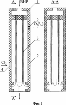
Figure 1 shows an embodiment of counter-current generator of singlet oxygen from the solution injector, in each hole (or tube) which passes through two filaments along the edges of the hole with a gap therebetween. In the section A-A shows the profile obtained solution jet.
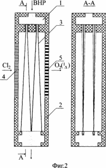
Figure 2 shows an embodiment of cross singlet oxygen generator, which of the holes (or tubes) solution injector thread located at an angle to each other. In the section A-A shows the profile obtained solution jet.
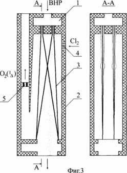
Figure 3 shows an embodiment of the continuous-flow generator of singlet oxygen, wherein one strand of holes (or tubes) intersects injector solution from another thread holes (or tubes) of a solution injector. In the section A-A shows the profile obtained solution jet.
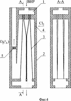
Figure 4 shows an embodiment of the continuous-flow generator of singlet oxygen, wherein one strand of holes (or tubes) concerns an injector solution from another thread holes (or tubes) of a solution injector. In the section A-A shows the profile obtained solution jet.
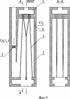
Figure 5 shows an embodiment of the continuous-flow generator of singlet oxygen, wherein one strand of the solution injector orifice fluidly connects smoothly with the thread holes of another solution injector to form a single filament. In the section A-A shows the profile obtained solution jet.
Figure 6 shows an embodiment of counter-current generator of singlet oxygen from the solution injector, each slotted hole which passes six strands arranged in a hole with a gap therebetween. In the section A-A shows the profile obtained solution jet.
Singlet oxygen generator containing a solution injector 1 with holes, the generator casing 2, the thread 3, a chlorine injector 4, the throttle valve-5.
Powered claimed singlet oxygen generator as follows. VNR solution (KOH + 2 H 2 O + H 2 O) supplied from the injector 1 solution in the generator housing upper part 2. In each hole (or tube) extends solution injector two yarns 3 arranged along the edges of the hole with a gap therebetween. The jet of solution emerges from the hole and then the solution injector is formed in the movement downwards along the yarn surface and between them. The filaments may extend from a solution injector holes parallel at an angle to each other, and a cross yarns or filaments from touching another hole injector solution. Furthermore, one strand of the solution injector holes may fluidly connect smoothly with the threads of the other openings solution injector to form a single strand of the same or smaller diameter.
 |
 |
 |
 |
 |
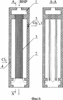 |
If one thread emerging from the hole parallel solution injector (1, 6) is formed between the common cylindrical jet expanding when moving down in the form of a cone. This significantly (more than 2-fold) increases stability of the jet portion length at the same pressure in the injector solution.
If one thread out of solution injector hole at an angle to each other of the arcs (2) then reduced proportional to the angle of the cylindrical portion of the jet length increases and length of a flat portion of the jet. This reduces the thickness profile of the jet, an increase in width, perimeter and area of the jet surface, which is accompanied by intense surface renewal jet ions HO -2 by increasing the jet perimeter.
If one thread hole injector solution from the other yarn traverse openings solution injector (3), the angle between the filaments is increased more and more proportional to the angle decreases the length of the cylindrical stream is increased and the length of the flat portion of the jet. This leads to a further decrease in the thickness profile of the jet, an increase in width, perimeter and area of the jet surface. This is followed by intense surface renewal jet ions HO -2 is not only due to the continuous increase in the perimeter of the jet, but also due to flow of the jet stream of solution intersections of threads and yarns themselves at an angle to the direction of the jet flow.
If one thread hole injector solution from another concern filaments solution injector holes (4), the length of the cylindrical portion of the jet is reduced and the length of the flat portion of the jet increased depending on the position of the point of touching filaments. Furthermore, the profile obtained solution spray in the place of contact filaments is not a thickening 3, reducing the distance between the jets.
If a single strand of the solution injector orifice fluidly connected smoothly with the other yarns of the solution injector openings to form a single strand of the same or smaller diameter (5), when the same advantages uniform wetting perimeter decreases in comparison with the jet touch one strand (Figure .4). This reduces the pressure loss during the flow of solution on filaments and increases the stability of the jet portion of the length of the jet surface area, surface reactivity and effectiveness of singlet oxygen generator.
Therefore, if a hole (or pipe) injector extends solution of at least two strands arranged on the edges of the hole with a gap between them, it not only directs the jet between the yarns, but also allows control and change the jet flow as desired geometric characteristics of the jet. This makes possible the realization of different types of generators of singlet oxygen with increased reaction surface and the work efficiency in comparison with generators of singlet oxygen and free jets on single filaments.
Input chlorine (Cl 2) as a singlet oxygen generator is from chlorine injector 4. When moving stream of chlorine (Cl 2) between the jets VNR solution (KOH + 2 H 2 O + H 2 O) occurs chlorination reaction of the alkaline solution of hydrogen peroxide to form singlet oxygen O 2(1 ![]() ) And recycling chlorine. The generated singlet oxygen O 2(1
) And recycling chlorine. The generated singlet oxygen O 2(1 ![]() ) Emerges from generator of singlet oxygen through the throttle valve 5, to reduce the pressure.
) Emerges from generator of singlet oxygen through the throttle valve 5, to reduce the pressure.
The claimed technical solution to improve the efficiency, reliability and work to expand the technological capabilities of the application of singlet oxygen generator.
CLAIM
1. The singlet oxygen generator, comprising a housing, the injector chlorine -drossel solution injector valve and with holes (or tubes) in each hole thread passes on the surface of which is formed by the jet and the filament bundles together form jets, characterized in that hole (or pipe) injector extends solution of at least two strands arranged on the edges of the hole with a gap therebetween.
2. singlet oxygen generator according to claim 1, characterized in that the thread of the injector hole at an angle out of solution together.
3. singlet oxygen generator according to claim 2, characterized in that the threads of one cross hole injector solution from another thread hole injector solution.
4. singlet oxygen generator according to claim 2, characterized in that the thread holes of one solution relating injector holes filaments from a solution of another injector.
5. singlet oxygen generator according to claim 2, characterized in that the threads of one solution injector holes are connected with the threads of the other openings solution injector to form a single filament.
print version
Publication date 28.02.2007gg


Comments
Commenting, keep in mind that the content and the tone of your messages can hurt the feelings of real people, show respect and tolerance to his interlocutors, even if you do not share their opinion, your behavior in terms of freedom of speech and anonymity offered by the Internet, is changing not only virtual, but real world. All comments are hidden from the index, spam control.