| section Home
Production, Amateur Radio amateur Model aircraft, rocket- Useful, entertaining |
Stealth master
Electronics Physics Technologies invention |
space Mystery
Earth Mysteries Secrets of the Ocean Stealth section Map |
|
| Use of material is permitted for reference (for websites - hyperlinks) | |||
Navigation: => |
Home / Products Patents / In the section of the catalog / back / |
|
INVENTION
Russian Federation Patent RU2260077
![]()
Staszewski UNIT II To split water into hydrogen and oxygen
Name of the inventor: Staszewski Ivan
The name of the patentee: Staszewski Ivan
Address for correspondence: 352243, Krasnodar region, Novokubansk, street. Leningradskaya, 19, kv.116, II Staszewski
Starting date of the patent: 2004.01.28
The invention relates to electrochemical industry. A device for separating oxygen from hydrogen formed as a vacuum container equipped with a float chamber, a vacuum controller, vacuum pump and outlet pipelines. The upper part of the electrolytic tank is connected by means of the inlet tube to the middle portion and the vacuum container by means of the outlet tube through the electric pump - the lower vacuum container base. The float chamber with reed contacts, the float and the plates of the permanent magnet is configured to automatically remove condensate from the vacuum container into the container of the cell. Output pipelines vacuum container connected to the burner through the vacuum pumps and valves, and the vacuum regulator is equipped with an arrow of a permanent magnet, in which the movement perimeter located reed switches are connected to a vacuum pump with an electric circuit and adapted to magnetic field interactions arrows reed switches for creating and maintaining a specified vacuum parameters and control of the pump. Part of the electrode is made of nickel with the possibility of combining the functions of the electrode and the catalyst and the electrolytic tank tray provided with ultrasonic or infrasonic generator. Technical effect - a simplified design, increased productivity, expansion of technological capabilities, improve the quality of hydrogen separation from oxygen, automatic removal of condensate from vacuum cylinder in capacity of the cell, improving the reliability and durability of the vacuum regulator.
DESCRIPTION OF THE INVENTION
The invention relates to electrical industry, and can be used to produce low-cost high-calorie fuel conduit and oxygen directly from water for steam boilers supply vehicles, internal combustion engines and other machinery.
A device for the break down of water into hydrogen and oxygen, comprising a sealed container filled with an electrolyte electrolytic cell in which the battery is installed stainless steel electrodes interconnected through the dielectric material of the washers by means of bolts and nuts. The anodes and cathodes respectively connected in series between an AC source and through rotating converters, generator of electric pulses and electric switches. The first electrolytic tank inlet tube connected to a vessel containing distilled water through the level controller. A second inlet tube connected to a container of liquid through the dispenser alkali equipped with timers and a solenoid, and the capacitance device is connected to electrolyzer for separating hydrogen from oxygen. / RUSSIA Patent 2227177 C2, IPC C 25 B 1/04, of 27.01.2004 /.
A disadvantage of the known technical solutions is the complexity of design of the device for separating hydrogen from oxygen, poor productivity, poor quality of the separation of hydrogen from oxygen.
The invention aims to simplify the construction, improved performance, expansion of technological capabilities, improved quality of separating hydrogen from oxygen, automatically remove condensate from the vacuum container into the container electrolyzer improved reliability and durability of the vacuum regulator.
This object is achieved in that the device for separating oxygen from hydrogen formed as a vacuum container equipped with a float chamber, a vacuum regulator and vacuum pumps, pipelines output upper part of the container is connected to the electrolyzer by means of the inlet tube to the middle portion of the vacuum container using an exhaust tube through the electric pump with the lower base of the vacuum bottle. The float chamber with reed contacts, the float and the plates of the permanent magnet is configured to automatically remove condensate from the vacuum container into the container of the cell. Output pipelines vacuum container connected to the burner through the vacuum pumps and valves, vacuum regulator is equipped with an arrow of a permanent magnet on the perimeter of movement which are located reed switches are connected to a vacuum pump with an electric circuit and adapted to cooperate magnetic field arrows reed switches to create and maintain a set vacuum parameters and control of the pump. In this part of the electrode is made of nickel, with the possibility of combining the functions of the electrode and the catalyst and the electrolytic tank tray provided with ultrasonic or infrasonic generator. Electrodes can be made plate, perforated, corrugated, brushy mesh, cell, cell cell, cell Grebeshkova tube of the outer and inner tubes have a cross-section in the shape of a square, circle, oval, rhombus, polygon, made in the form of multi-storey shelving installed in rows on different levels so that one row electrodes includes grooves in the other row, and rows between the shelves there is a gap and different polarity. Capacity electrolysis may be provided with a compressor and a vacuum valve.
The novelty of the claimed technical solution as compared with the patent 2227177 due to the fact that due to the use of different electrodes is provided an extension of technological possibilities.
By using a vacuum cylinder without diaphragms, without bypass pipes and valves, and connect it to the upper part of the electrolyzer by means of two tubes, wherein one tube is connected to the middle vacuum container, and the other - the lower vacuum container base, the output vacuum cylinder tube connected to the burner through the vacuum pump, provides improved quality of separation of hydrogen from oxygen, simplifying design and automatically remove condensate from the tank to the electrolytic cell.
Through the use of ultrasound or infrasound generator in the electrolysis provides improved performance.
Through the use of compressor and vacuum valve expanding technological capabilities.
By making the part of the combination provided nickel electrodes and electrode catalyst functions, thereby increasing productivity.
Through the application of a magnetic needle vacuum regulator and reed switches provided the interaction of the magnetic field of the arrow with reed switches for creating and maintaining a specified vacuum parameters and control of the operation of vacuum pumps.
Due to the vacuum in the electrolytic tank is provided extract hydrogen and oxygen during electrolysis by means of vacuum pumps.
Due to the vacuum in the vacuum cylinder capacity provides improved separation of hydrogen from the oxygen from the difference between the proportion of gas.
Under the influence of overpressure in the container by means of electrolytic extraction of hydrogen compressor is provided, and oxygen during electrolysis.
Due to the vacuum valve provides simplification of the design liquid level controller, improving reliability and durability.
In the investigation of the claimed technical solution by a patent, scientific, scientific and technical content not found such a combination of features that allows you to judge the novelty and essentiality of the claimed features.
BRIEF DESCRIPTION OF DRAWINGS
 |
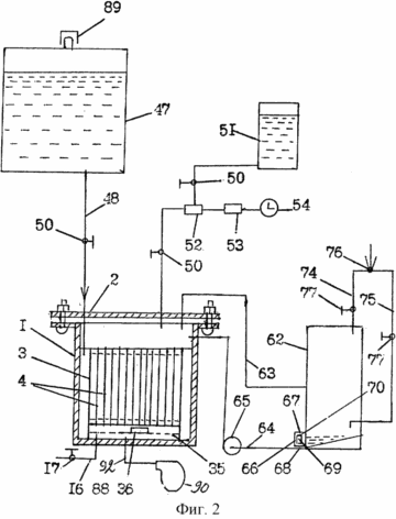 |
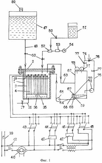
1 shows a diagram of the water electrolysis apparatus; Figure 2 shows the electrolysis cell water circuit provided with a compressor and a vacuum valve.
 |
 |
 |
 |
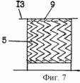 |
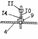
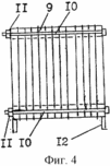
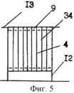
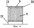
3 is a connection diagram of electrodes in the battery; 4 and 5 shows a battery plate electrodes; 6 and 7 - the same with corrugated electrodes.
 |
 |
 |
 |
 |
 |
 |
 |
 |
 |
 |
 |
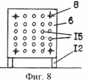
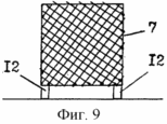
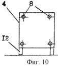
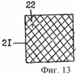
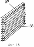
8 - the same as with perforated electrodes; 9 - same cell with electrodes; Figure 10 shows a longitudinal view of the electrode plate; 11 and 12 depict brushy electrodes; 13 and 14 and 15 depict cell electrodes; Figure 16 shows connection electrodes thyroid cell electrodes; Figure 17 shows cell cell electrodes; 18 and 19 depict shelf electrodes.
 |
 |
 |
 |
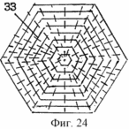 |
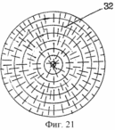
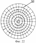
Figure 20 shows the tubular cylindrical electrodes of the cell capacity; 21 and 22 depict cylindrical needle electrodes; Figure 23 shows the square needle electrodes; Figure 24 shows polyhedral needle electrodes.
 |
 |
 |
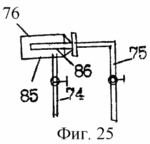
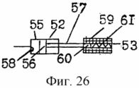
Figure 25 shows a burner device for detonating gas; Figure 26 shows a diagram of the device and dispenser solenoid; Figure 27 shows a pectinate electrode.
 |
 |
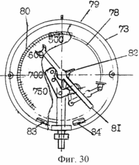 |
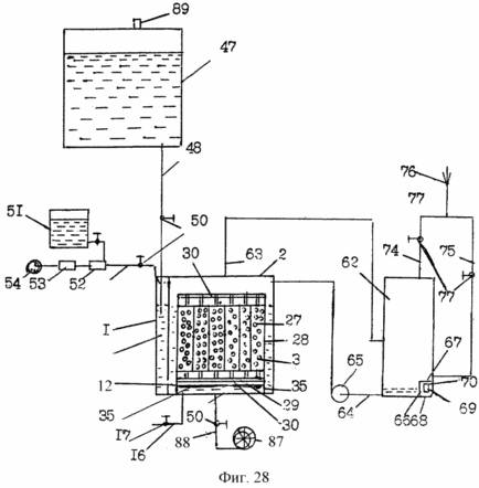
Figure 28 shows a battery charger with tubular electrodes; Figure 29 shows a longitudinal section of the tubular electrode; Figure 30 depicts the vacuum control device.
The cell consists of a sealed water tank 1 made of stainless steel. Container 1 has a lid 2. Inside the container 1 is mounted battery 3, made from either plate 4, 5 or corrugated plate, perforated plate or 6 or 7 mesh stainless steel electrodes. These electrodes are at the corners of the opening 8, through which they are rigidly connected to each other through the washer 9 from the dielectric material by means of bolts 10 and nuts 11. The battery 3 is provided with legs 12 and side stops 13 of dielectric material. Between the nuts 11 and washers 9 are spring-loaded slotted washer 14 between the electrodes 4 or 5, 6, 7 there is proper clearance and different polarity. The electrodes may be arranged to move the opening 15 of the electrolyte. The electrodes 4, 5, 6, 7 may be made of stainless steel by deformation of the die pressure by means of hot stamping sheet or cast on a casting machine under pressure in a vacuum. At the bottom of the electrolytic tank 1 there is a drain pipe 16 with a valve 17, adapted to drain the electrolyte in winter when cold in order to prevent the defrost system.
Electrodes in the battery 3 may be executed in the second embodiment. The second embodiment is the same as the first, which is characterized by the fact that the electrodes 18 are brushy, needles 19 which are directed in the opposite base 20 disposed plates. Between the base plate 20 and the ends of the needles 19 there is proper clearance and different polarity. Brushy electrodes 18 are made on cast lettered pressurized machines in vacuo.
Electrodes 18 may be formed in the third embodiment. The third embodiment is the same as the second embodiment differs in that the electrodes 18 brushy needles 19 with their ends facing each other. Between the ends of the needles 19 there is proper clearance and different polarity.
The electrodes 21 in the battery 3 may be executed in the fourth embodiment. The fourth embodiment is the same as the third embodiment differs in that cell electrodes 21 are provided. Cells 22 can have a cross sectional shape of a circle, oval, square, rhombus, polyhedron, machines manufactured by casting under pressure in a vacuum. Between the cell electrodes 21 installed brushy electrodes 18, on both sides of the needle 19 installed in the center of each cell 22. Between the needles 19 and the cell walls 22 there is proper clearance and different polarity.
The electrodes 23 in the battery 3 may be executed in the fifth embodiment. The fifth embodiment is the same as the fourth embodiment differs in that the electrodes are in the form of cells 23 containing a diaphragm 24 inside the bee honeycomb similarly. Of cells 23 between electrodes 18. The electrodes are mounted brushy Cell cell electrodes 23 have a cross section in the shape of a circle or an oval, or a square or a rhombus, or a polygon. Cell walls between electrodes 22, 23 are brushy electrodes 18 on both sides of the needle 19 brushy electrodes 18 are mounted in the center of each cell 22 between the needles 19 and cell walls 22 and the diaphragm 24 has a proper gap and different polarity. Electrodes 23 and 18 are made on casters cast under pressure in a vacuum.
The electrodes 25 in the battery 3 may be executed in the sixth embodiment. The sixth embodiment is the same as the fourth embodiment differs in that the electrodes 25 are in the form of a comb electrode cell, containing a longitudinal plate with a single row of needles 26. rigidly fixed brushy electrodes 25 have only one row of needles and electrodes brushy many rows of needles 19. Needles pectinate electrode cell 25 installed so as to give the proper form cells 22, such as a square, circle, oval, diamond shaped, polyhedron. Between cell pectinate electrodes 25 installed on both sides of brushy electrodes 18, 19 of the needle set in the center of each cell 22 of the electrodes 25. Between the needles 19 and the cell walls 22 of the electrodes 25 has the proper clearance and a different polarity. Electrodes 18 and 25 are made on casting machines under pressure in a stainless steel vacuum.
The electrodes 27 in the battery 3 may be fabricated in the seventh embodiment /fig.5/. The seventh embodiment is the same as the embodiments 2-6, differs therefrom in that the electrodes 27 are made of the outer tube 28 and inner tube 29. The outer tube 28 are interconnected to a battery 3 having a cross-sectional shape of the holes in the circumference of an oval, square , rhombus, polyhedron, which are located inside the inner pipe 29 having a cross-sectional view similar to the outer pipe 28. inner tube 29 is rigidly secured to the frame 30. between the outer 28 and inner tube 29 has an appropriate gap and different polarity. The batteries 3 are provided with legs 12 and side stops 13 of dielectric material.
The electrodes 32 in the battery 3 may be executed in the eighth embodiment. The eighth embodiment is the same as the embodiments 1-7, differs therefrom in that the electrodes 32 are in the form of cylinders, installed in a cylindrical container coaxial to each other. Between them there is proper clearance and different polarity.
Electrodes 33 may be made in the ninth embodiment. The ninth embodiment is the same as the eighth embodiment differs in that the electrodes 33 are formed in the shape of a polyhedron arranged in parallel to each other in a multifaceted capacity. Between them there is proper clearance and different polarity.
The electrodes 34 in the battery 3 may be executed in the tenth embodiment. The tenth embodiment is the same as the embodiments 1-9, differs therefrom in that a portion of the electrode is made of nickel. These electrodes are located in the electrode made of stainless steel. Nickel electrodes are used as catalysts and at the same time, are capable of coming into engagement with an intermediate electrolyte substance, they restore their properties by the end of conversion.
Electrodes in the battery 3 may be executed in the eleventh embodiment. The eleventh embodiment is the same as the embodiments 1-10 differs therefrom in that the pallet 35 containing the appropriate diameter hole, and installed rigidly fixed ultrasound or infrasound generator 36 configured to create and generate elastic waves with an oscillation frequency of 20 kHz up to 1 GHz or less than 16 Hz in the electrolysis process to improve productivity.
The cell 37 of the battery 3 may be executed in embodiment 12. A twelfth embodiment is the same as the first embodiment, differs in that the electrodes 37 are in the form of shelves 38. Shelf multistory electrodes 37 are set in rows on different levels so that one row electrodes 37 included in the other row a gap and between the shelves and series has the proper clearance and a different polarity.
Anodes electrodes sequentially interconnected, the cathodes electrodes are connected in series with each other and the AC source 39 by means of an electrical circuit through the rotating converters 40, the generator 41 of electric pulses and the electrical switches 42, 43, 44, 45, 46 are configured to convert AC to direct current, low voltage current - high voltage current, creating electrical impulses proper frequency and duration, and opportunities to work in different ways: for example, if the rated voltage or rated voltage in a pulsed mode, or at high voltage. Electrolytic tank 1 is connected with the container 47 of distilled water by means of a tube 48. At the end of the tube 48 is installed a liquid level controller, designed in the form of a check valve 49. On tube 48 is a valve 50 adapted to maintain a predetermined liquid level in the electrolytic tank 1 in level control assistance - the check valve 49. The upper part of the electrolytic vessel 1 is connected to the lower header tank 51 filled with a liquid alkaline / caustic sodium or potassium hydroxide / through the dispenser 52. The dispenser 52 is provided with a solenoid 53 and a time relay 54 is movable liquid alkali doses over period of time. The dispenser 52 consists of a cylinder 55, piston 56, rod 57, the microswitch 58. The solenoid 53 includes an inductor 59, a core 60, a spring 61.
Apparatus for separating hydrogen from the oxygen carried into the vacuum container 62 form comprising inlet tubes - pipeline 63 and an outlet tube 64. The upper part of the electrolytic vessel 1 is connected with the middle vacuum cylinder 62 by means of pipeline 63 and the upper part of the electrolyzer and connected to the lower vacuum base 62 by means of the cylinder tube 64 via an electric pump 65. The vacuum cylinder or balloon 62 near the float chamber 66 is set, in which the upper and lower substrates mounted reed switches 67 and 68, and 66 mounted in the float chamber 69, on its upper and lower bases of the set plate 70 a permanent magnet adapted to move from hydrogen and oxygen in the electrolytic vessel 1 vacuum tank 62 and automatically remove condensate from the vacuum container 62 in the electrolytic tank 1 in the initial position. The vacuum cylinder 62 is provided with vacuum pumps 71 and 72, vacuum controller 73 and the pipelines 74 and 75, adapted to accelerate the extraction of water the hydrogen and oxygen during electrolysis and improve the hydrogen separation from oxygen and move them into the burner 76 via pipelines 74 and 75 and simplify the structure. Piping 74 and 75 are provided with valves 77 configured to control the supply of a gaseous fuel burner 76 of hydrogen and oxygen. Vacuum gauge and regulator 73 are combined and are made of hollow tubes latunevoy 78, wherein the cavity communicates with the reduced pressure suction cylinder 62. Latunevaya tube 78 located in a cylindrical box 79 of polymeric material 80 is provided with a scale, graded (in mm) of mercury. A loose end of the tube 78 is connected with an arrow 81 by means of the gear 82, made of bronze. Arrow 81 gauge made of a permanent magnet. The box 79 around the perimeter of the path of movement of the arrow 81 are arranged in appropriate locations, and are rigidly fixed reed switches 83 and 84 adapted to cooperate with the magnetic field of the arrow 81 with reed switches 81 to automatically adjust and maintain a predetermined low pressure limit parameters and control the operation of the vacuum pump 71 and 72. reed switches 83 are configured to trip the circuit supplying the vacuum pumps 71 and 72, and the reed switch 84 operates on the electric circuit feeding the chains 71 and vacuum pump 72. The burner 76 consists of two tubes 85 and 86. tube 85 is connected to the pipeline 74, in which the hydrogen is moved, and the tube 86 is connected to the gas conduit 75 by which oxygen is moved.
Device for splitting water into hydrogen and oxygen can be performed in the second embodiment. The second embodiment is the same as the first embodiment, differs in that the container 1 is provided with a compressor 87 and a pipe 88. Volume 47 is filled with distilled water, is connected with the container 1 by means of the electrolytic pipe 48. Volume 47 is clogged stopper 89 is movable distilled water from container 47 to container 1 by gravity and maintain the desired liquid level in the vessel 1 using the vacuum valve.
The device operates as follows.
Opening the valves 50, 70 on the tube 48 and the pipelines 74 and 75 completes the electrical circuit supplying the time relay 54 and the flat plate 4, or 5, corrugated plate, perforated plate or 6 or 7 mesh or brushy 18 or cell 21, or cell cell 23 or cell pectinate 25 or tube 27 / the outer 28 and inner 29 / electrodes or cylinder 32 or multifaceted 33, a shelf 37, the ultrasonic generator 36 or infrasound generator, through power switches 42 and 43 through the rotating converters 40. in this dynamoelectric converter 40 converts alternating current to direct current at the rated voltage and feeds the electrodes 4 or 5, 6, 7, 18, 21, 23, 25, 27, 32, 33, 34, 37. Distilled water tank 47 from moves downward through the tube 48 into the container 1, the electrolyzer 1 by gravity. Simultaneously, air is moved by means of bubbles from the bottom up tube 48 filling the proper amount of vacuum in the vessel 47. Once the distilled water fills the tank in proper volume of the electrolytic cell 1 up to the level of the tube 48, the lower end of the tube 48 is closed and prevents fluid movement upward air into the container 47 . The vacuum in the container 47 prevents fluid movement from the top downwards. Movement of liquid from container 47 stops. After a time interval timer relay 54 opens the electrical circuit supplying the solenoid 53. The solenoid 53 disappears magnetic field under the action of the spring 61 the core 60 moves the piston 56 by means of the rod 57 along the cylinder portion 55. The dosage of liquid alkali / potassium hydroxide or sodium hydroxide / moves electrolytic tank 1 in the tube. As soon as the piston 56 moves to the microswitch 58, the microswitch 58 closes the electrical circuit supplying the coil 53 and the relay 54. In time the solenoid 53 a magnetic field. The solenoid 53 operates and moves the piston 56 to its original position. When passing an electrical current through the electrodes 1 electrolyzer electrochemical processes occur to the electrodes of the ion motion. Positively charged ions move toward the cathode and the anode oxygen ions move to the cathode. The electrical current through an external circuit is the process of movement of the ions from the anode to the cathode. At the anode and cathode of the ion neutralization reaction takes place, which leads to the formation of atoms and molecules and release of substances on oxygen the anode and the cathode - hydrogen. In distilled water no salt and other impurities, however do not remain on the electrodes and the precipitation of salts attacks. The distilled water is not enough stable molecular and ionic bonds. In alkaline electrolysis of distilled water is faster destruction of molecular and ionic bonds and the splitting of water into hydrogen and oxygen than when using tap water. Vacuum regulator 73 adjusts and maintains the parameters specified vacuum in the vacuum tank 62 and controls the operation of vacuum pumps 71 and 72 in the automatic mode. Vacuum pumps 71 and 72 working create underpressure / vacuum / cylinder 62 in the vacuum vessel 1 and the cell. Due to the vacuum in the container 1 is extracted electrolyzer 1 hydrogen and oxygen from an electrolyte during electrolysis accelerates the splitting of water into hydrogen and oxygen, and movement in the vacuum cylinder 63. The suction cylinder 63 is separated from the hydrogen by the difference of oxygen gas specific gravity and moves by means of vacuum pumps 71 and 72 into the burner 76 via pipelines 74 and 75.
Electrodes in the battery 3 can be operated in the second embodiment. The second embodiment is the same as the first, it differs in that the electrodes 18 are brushy, needles 19 are directed to the base plate 20 located on the opposite side. Between the base plate 20 and the ends of the needles 19 there is proper clearance and different polarity.
The electrodes 18 in the battery 3 can be operated in the third embodiment. The third embodiment is the same as the second embodiment differs in that the ends of the needles 19 brushy electrodes 18 facing each other. Between the ends of the needles 19 there is proper clearance and different polarity.
The electrodes 21 in the battery 3 can be operated in the fourth embodiment. The fourth embodiment is the same as the third embodiment differs in that cell electrodes 21 are provided. Cell electrodes 21 in cross section may be shaped cells 22 in the form of a circle, oval, square, rhombus, polygon. Between the cell electrodes 21 installed brushy electrodes 18 on both sides of the needle 19 set in the center of each cell 22. The needles 19 between walls 22 and cell electrodes 21 have proper clearance and different polarity.
The electrodes 23 in the battery 3 can work in the fifth embodiment. The fifth embodiment is the same as the fourth embodiment differs in that the electrodes 23 are in the form of cellular cell electrodes inside the cells 24 has a similar aperture in the bee cells. Cells in the electrodes 23, 22 may have a cross section in the shape of a circle, oval, square, rhombus, polygon. Between the electrodes 23 are electrodes 18 brushy, brushy installed needle electrode 18 in the center of each cell 22. Between the needles 19 and the cell walls 22 and the diaphragm 24 has the proper clearance and a different polarity.
The electrodes 25 in the battery 3 can be operated in the sixth embodiment. The sixth embodiment is the same as the fourth embodiment differs in that the electrodes 25 are in the form of a comb cell electrodes 25 having a plate with a row of needles 26 mounted in such a way as to make the cells 22 form a circle, oval, square, rhombus, polygon. Between cell pectinate electrodes 25 installed brushy electrodes 18 of the needle 19 installed in the center of each cell 22 of the electrodes 25. Between the electrode needles 19 and the cell walls 22 there is proper clearance and different polarity.
The electrodes 27 in the battery 3 can be operated in the seventh embodiment. The seventh embodiment is the same as the embodiments 2-6, differs therefrom in that the electrodes 27 are tubular. The outer tube 28 are interconnected by a single frame in the battery 3. Inside the outer tube 28 are disposed inside the pipe 29 located coaxial to each other. Cross section of pipe may have a shape of a circle, oval, square, polygon, rhombus. Inner tube 29 is rigidly fixed to the frame 30. Between the outer and inner tubes 28, 29 have the proper clearance and a different polarity. The battery 3 is provided with legs 12 and side stops 13 of dielectric material.
The electrodes 32 in the battery 3 can be operated in the eighth embodiment. The eighth embodiment is the same as the embodiments 1-7, differs therefrom in that the electrodes 32 are in the form of cylinders, installed in a cylindrical container coaxial to each other. Between them there is proper clearance and different polarity. The electrodes 33 in the battery 3 can be operated in the ninth embodiment. The ninth embodiment is the same as the eighth embodiment differs in that the electrodes 33 are in the form of polyhedra, polyhedral container installed in parallel with each other. there is proper clearance and different polarity between them.
The electrodes 34 in the battery 3 can be operated in the ninth embodiment. The tenth embodiment is the same as the embodiments 1-9, differs therefrom in that a portion of the electrode is made of nickel, and some - of stainless steel, the electrodes are interconnected. Nickel electrodes act as a catalyst. Adapted to coming into interaction with intermediate electrolyte substance, after electrolysis, they restore their properties.
Electrodes in the battery 3 may be executed in the eleventh embodiment. The eleventh embodiment is the same as the embodiments 1-10 differs therefrom in that the pallet 35 is fixed and rigidly mounted ultrasound or infrasound generator 36 configured to create and generate elastic waves. During electrolysis, the generator 36 generates elastic waves which interact with the electrochemical processes of the ions, results in faster destruction of the molecular and ionic bonds, accelerates the decomposition of water into hydrogen and oxygen, increases productivity and reduces energy consumption for water splitting.
37 electrodes in the battery 3 can be made in Bat twelfth embodiment. A twelfth embodiment is the same as the embodiment 1, it differs in that the electrodes 37 are in the form of multi-storey shelving. Shelves electrodes installed at different levels so that one row of the shelves 37 included in the other row slots shelves. Between the rows of shelves there is proper clearance and different polarity. The electrodes 37 may be arranged in both vertical and horizontal planes.
The electrodes 4, 5, 6, 7, 18, 21, 23, 25, 27, 33, 37 may operate in the second mode. The second mode is the same as the first mode, it differs in that the electrodes are connected to a source of AC dynamoelectric 39 through converter 40, the generator 41 of electric pulses and electric switches 42 and 44. This alternating current is converted into direct current. The generator 41 of electric pulses create electrical pulses to the electrodes at the rated voltage of the electric current.
The electrodes 4, 5, 6, 7, 18, 21, 23, 25, 27, 33, 34, and 37 can be operated in the third mode. The third mode is the same as the first mode, it differs in that the electrodes are connected to an AC source 39 through the rotating converters 40 and electrical switches 42 and 45. This alternating current is converted into direct current, low voltage current is converted to high voltage current tens of thousands of volts.
Vacuum regulator 73 operates as follows. When the vacuum pumps 71 and 72 in the vacuum tank 62 and the electrolytic tank 1 creates a low-pressure vacuum. Vacuum tubes 73 communicate with the controller latunevoy hollow tube 78, the pressure variation hollow tube 78, vacuum regulator 73 somewhat twisted, its movement is transferred by means of the transmission mechanism 82 to change the position of the arrow 81. The arrow 81 is rotated and its magnetic field interacts with the permanent magnet reed 83. Under the influence of the magnetic field of the arrow 81 the reed switch 83 opens the circuit supplying the vacuum pumps 71 and 72. vacuum pumps 71 and 72 stop working. By means of the water electrolysis water is decomposed into hydrogen and oxygen. Hydrogen and oxygen are moved from one tank to the vacuum elektralizera balloon 62 and fills it. The vacuum tank 62, hydrogen is separated from oxygen in a vacuum. Hydrogen is moved upward, and oxygen is lowered from the specific gravity difference gases. From the vacuum bottle 62 is moved to the burner 76, hydrogen moves through the pipeline 74, oxygen - by pipeline 75. This oxygen is moved to a central pipe 86, and hydrogen - in the interspace between the tubes 86 and 85 into the burner 76. As will increase pressure above the set parameters in the vacuum tank 62, the pressure in the tube is transferred to a vacuum controller 73. Latunevaya tube 78 straightens out and is moved to the initial position when the pressure increases. As soon as the pressure reaches the proper setting, the arrow 81 is moved to the reed switch 84 and its magnetic field acts on the reed switch 84. The reed switch 84 completes the electrical circuit supplying the vacuum pumps 71 and 72. The vacuum pump starts and move hydrogen and oxygen. Vacuum pump moves hydrogen from the vacuum container 62 in the burner 76 and the vacuum pump 72 moves the oxygen from the vacuum container 62 to the burner 76. Blasting gas can be used as fuel in boilers for heating residential and industrial buildings, in the steam boilers, steam engines, steam boilers in power plants, internal combustion engines and other machines. During electrolysis, and handling of hydrogen and oxygen on the electrolytic tank 1 in the vacuum tank 62 is supplied and a portion of water vapor. Pairs cooled and transformed into a condensate / distilled water. As soon as the condensate level rises to the level of the upper reed switch 67, the float pops up, moving from bottom to top in the float chamber 66, the float 69 by the magnetic field of the permanent magnet interacts with the reed 67. The reed switch 67 completes the electrical circuit supplying the electric pump 65. The electric pump 65 moves the condensate from vacuum bottle 62 into the electrolytic vessel 1 through the tube 64 to its original position. As soon remove all the condensate, the float 69 is moved downward in the float chamber 66 and the magnetic field of the permanent magnet, which is located on the float 69 interacts with the reed 68. The reed switch 68 opens the circuit supplying the electric pump 65. The pump 65 stops operating.
Device for splitting water into hydrogen and oxygen can be operated in the second embodiment. The second embodiment is the same as the first embodiment, it differs in that the electrolytic cell is provided with a compressor 87 Veda /fig.28/. Completes the electrical circuit supplying the compressor 87. The compressor 87 is pressurized, the compressed air pressure of at least 0.2 MPa / 2 kgf / cm 2 / and produces over the capacity of the cell 1 under the pallet 35. Compressed air is evenly distributed under the pallet and moves through opening the pallet 35 in upward help bubbles. Air bubbles absorb the bubbles of hydrogen and oxygen produced during electrolysis, and detach them from the electrolyte or water. Hydrogen and oxygen are moved in the vacuum tank 62 due to the difference of specific weights of gases. There hydrogen is separated from oxygen by the action of the difference of the specific gravity gases. Hydrogen moves through the pipeline 74, and oxygen through the pipeline 75 to the burner 76.
CLAIM
1. Device for splitting water into hydrogen and oxygen, comprising a sealed, filled container electrolyte electrolyser, which is installed in the battery electrodes made of stainless steel, connected to each other through a dielectric material washer with bolts and nuts, which cathodes and anodes, respectively, successively connected together and to a source of AC power via the rotating converters, electrical pulse generator and electrical switches, the first inlet tube electrolytic tank is connected to a container of distilled water through the level controller, a second inlet tube connected to a vessel containing the liquid alkali through the dispenser, provided with a solenoid and relay time and capacity electrolyzer is connected with the unit for separating hydrogen from oxygen, characterized in that the device for the separation of hydrogen from the oxygen formed as a vacuum container equipped with a float chamber, a vacuum controller, vacuum pump and outlet pipelines, upper electrolytic tank connected by means of the inlet tube to the middle part of the vacuum container and by means of the outlet tube through the electric pump - with a lower base vacuum cylinder float chamber with reed contacts, the float and the plates of the permanent magnet is configured to automatically remove condensate from the vacuum container into the container electrolyzer output pipelines vacuum container connected to the burner through the vacuum pumps and valves, and the vacuum regulator is equipped with an arrow of a permanent magnet, in which the movement perimeter located reed switches are connected to a vacuum pump with an electric circuit and adapted to interaction between the magnetic field arrows reed switches for creating and maintaining a predetermined vacuum parameters and control the operation of pumps, with a portion of the electrode is made of nickel with the possibility of combining the functions of the electrode and the catalyst and the electrolytic tank tray provided with ultrasonic or infrasonic generator.
2. The apparatus of claim 1, wherein the electrodes are plate, perforated, corrugated, brushy mesh, cell, cell cell, cell scalloping.
3. Device according to claim 1, characterized in that the electrodes are formed as outer and inner tubes of different polarity, the cross section of which can take the form of a circle, oval, square, rhombus, polygon, wherein the inner tube is rigidly secured to the frame and between inner and outer tubes there is a gap.
4. Device according to claim 1, characterized in that the electrodes are in the form of multi-storey shelving mounted in rows on different levels so that one row electrodes includes grooves in the other row, has a different polarity and gap between the shelves and rows.
5. The apparatus according to claim 1, characterized in that the electrolysis tank is equipped with a compressor and a vacuum valve.
print version
Publication date 01.03.2007gg


Comments
Commenting, keep in mind that the content and the tone of your messages can hurt the feelings of real people, show respect and tolerance to his interlocutors, even if you do not share their opinion, your behavior in terms of freedom of speech and anonymity offered by the Internet, is changing not only virtual, but real world. All comments are hidden from the index, spam control.