| section Home
Production, Amateur Radio amateur Model aircraft, rocket- Useful, entertaining |
Stealth master
Electronics Physics Technologies invention |
space Mystery
Earth Mysteries Secrets of the Ocean Stealth section Map |
  |
| Use of material is permitted for reference (for websites - hyperlinks) | |||
Navigation: => |
Home / Products Patents / In the section of the catalog / back / |
|
INVENTION
Russian Federation Patent RU2199492
![]()
DEVICE FOR CONTINUOUS PROCESSING OF SEA WATER
On discharge from the HER demineralized water, hydrogen, oxygen, metals
And other compounds, dividers IONS FOR SEPARATION OF SEA WATER IN THE MAGNETIC FIELD demineralized water, anolyte and catholyte, isolating-CONVERTER FOR BRANCH hydration shell from the ions and neutralize ON THEM electric charge and the hydrogen generator
Name of the inventor: Alyanov MI .; Vasyuta MM
The name of the patentee: Alyanov Mikhail Ivanovich; Vasyuta Maria M.
Address for correspondence: 153013, Ivanovo, st. Cavalry, 46A, kv.40, MI Alyanovu
Starting date of the patent: 2000.01.11
The invention relates to a continuous processing technology with seawater release therefrom of fresh water and raw materials. An apparatus for continuous processing of seawater divider comprises series-connected ion neutralizer separator and the hydrogen generator constituting the first processing line. A second processing line to form a second separator-converter mixer-reactor and hydrogen generator, running at demineralised water and alkaline melt. ion separator for separating seawater to desalted water, catholyte and anolyte contains preliminary magnetization water section of a circular magnetic field and separation section configured as a central pipe to which the through slit diameter two smaller diameter conduit attached to separation of anolyte and catholyte . Separator-converter for separating the hydrate shell of anions and cations and neutralizing them of electric charges contains connections for input vaporous catholyte and anolyte conical mesh bearing positive and negative charges, and a converter having a metallic ball contact and the contact of the molten lithium or sodium. The hydrogen generator comprises a heat insulating housing with a reaction zone for interacting the molten lithium, and the water cooling system and with the reaction mass separation therefrom an aqueous solution of lithium hydroxide and hydrogen. Technical effect - extracting fresh water from sea water, hydrogen, oxygen, and other valuable products, carried out in a continuous process.
DESCRIPTION OF THE INVENTION
This invention - a group of inventions which are combined into a single unit and are aimed at obtaining raw materials from sea water by physico-chemical processes, which is exposed to seawater, continuously moving two technological lines.
The main objective of the present invention - the replacement of the entire planet fossil fuels Land (gas, petroleum products, coal, peat) on clean hydrogen fuel (pure hydrogen), but also to provide fresh water in industry and agriculture, but also the raw material for chemical and metallurgical industry.
We considered below full analog technology is none, t. To. In the literature there is no description of the process by which in a single and continuous technological cycle of sea water is released once a range of products listed above.
However, the manufacturing process includes many technical solutions, based on which, when combined in a single process, and created this invention.
1. In the prior art device for separating seawater for catholyte and anolyte demineralized water by a magnetic field with the magnetic flux is perpendicular to the water flow movement (SU 361981, 13.12.1972, C 02 F 1/48). However, our invention is structurally different from the present invention.
2. In the prior art and a device for magnetization of the magnetic field of a circular water described Klassen VI "Magnetization of water systems", Moscow: Chemistry, 1985, s.157-158. This invention solves the problem only by half, because It does not share water with anolyte - demineralized water - catholyte.
3. It is known that the interaction of the molten lithium and water is accompanied by an explosion, in addition molten lithium is a fire hazard substance ( "Chemistry and technology of rare and dispersed elements" KA Bolshakov, Part I, manual for schools, M .: Higher School, 1976, p.8, 75).
In the present invention, the process and structure of the hydrogen generator exclude conducting chemical reactions produce hydrogen in the volatile embodiment.
4. However, it is known that the conductivity of dielectrics, as is the water vapor rises sharply and impact ionization begins at high voltages (Short Chemical Encyclopedia, M .: Soviet Encyclopedia, 1961, p. 1184). On the separator grid-supplied power converter, which eliminates the impact ionization.
5. The apparatus for producing hydrogen by thermochemical decomposition of water containing a reaction zone and a heat exchanger (RU 204032, B 01 J 37/00, 27.07.95, 110) The closest analogue of claim. 4 of the hydrogen generator can be considered. This is a very different process, and it can not compete with the subject invention.
Solving the problem requires new high technologies, providing great speed of reaction between components reaction. The present invention is based on four specially developed methods that provide high rates of reaction between the reactants, up to the instantaneous reaction rate - neutralization of electric charges ions, without hydration shells to form the desired product.
For each method it has developed a special device, which passes the appropriate physico-chemical process.
The problem is solved in that the device for the continuous processing of seawater with separation therefrom demineralized water, hydrogen, oxygen, metals and other compounds comprises series-connected separator ions for separating seawater magnetic field on desalted water, anolyte and catholyte separator neutralizer for separating the hydration shell of cations and anions, and neutralizing the electrical charge on them and hydrogen generator for producing hydrogen by reacting a molten lithium and water, which form the first processing line. A second series-connected converter-separator, the reactor-mixer and the hydrogen generator, running demineralized water at alkaline melt and form a second processing line.
The separator for separating ions of seawater to desalted water, anolyte and catholyte comprises a conduit disposed in the magnetic field, magnetization of water prior circular section of the magnetic field produced by the coil of an electromagnet equipped with a device for the tangential entry of water. Section previously magnetized water separation by applying a magnetic field with a magnetic flux perpendicular to the direction of water movement, designed as a central pipe, through which slit the diameter of the two smaller diameter conduit connected to output anolyte and catholyte.
Separator-converter for separating the hydrate shell of anions and cations and neutralizing them of electric charges, it contains connected in series with one another feeder on the conical grid high voltage DC, a separator provided with spigots entering vaporous catholyte and anolyte two conical nets, carriers, respectively, positive and negative charges, two absorbers velocity vapor anolyte and catholyte and two guide cylinders for entering non-hydration shell of anions and cations in the converter and the converter comprising a low voltage DC generator and an external oscillator circuit, in which includes a metal pin and a ball of molten lithium or sodium.
The hydrogen generator comprises a heat insulating housing, wherein the reaction zone is provided for the interaction of water and molten lithium. The body and provided with cooling of the reaction mass cooled with cold isolation therefrom an aqueous solution of lithium hydroxide and hydrogen discharge pipes for hydrogen and aqueous lithium hydroxide. In addition, the generator has input connections anolyte and catholyte into the annulus of the reaction zone and the vapor withdrawal connections catholyte and anolyte provided with electrical heaters.
An apparatus for continuous processing of seawater with separation therefrom demineralized water, hydrogen, oxygen, metals and other compounds is based on two processes, comprising the following process steps.
FIRST INDUSTRIAL PROCESS
Step 1.
Separation of sea water under the action of a magnetic field into three fractions: Anolyte - demineralized water - catholyte
extending the process by the example of LiCl
a) LiCl dissociation of H 2 O
LiCl -> Li + + Cl - ( 1)
b) separating the seawater into separator ions under the influence of the magnetic field takes place as follows: 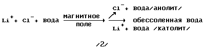
Stage 2.
Ways to use the anolyte and catholyte, obtained after separation from seawater desalinated water.
Ways to use anolyte and catholyte are as follows:
a) the anolyte and catholyte after ions exit the separator are mixed, and the mixed solution is sent back to the ocean, where it is up to the initial dilution of the salt concentration in the ocean;
b) the mixed solution in paragraph (a) shall be sent to the landfill for natural evaporation of water (for countries with a hot climate) in order to obtain a natural sea salt and further sending it for processing;
c) the catholyte and anolyte for individual pipelines are directed to deep processing enterprises in the chemical and metallurgical in order to obtain the desired products (individual, metal salts).
The first process is entered only desalinated water, and output - hydrogen and oxygen.
Step 3. Separation of aqueous LiOH solution into two fractions: the anolyte and catholyte.
reaction equation
LiOH -> Li + + OH - (4)
Li + + nH 2 O -> Li + 6H 2 O + (n-6) H 2 O (5)
OH - + nH 2 O -> OH - 6H 2 O + (n-6), H 2 O (6).
Step 4. Branch with the hydration shell of the ions.
reaction equation 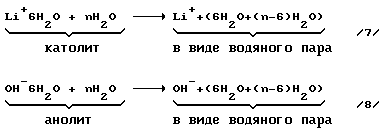
Stage 5. Neutralization of electrical charges on the ions Li + and OH - to form a lithium metal, water and oxygen.
reaction equation 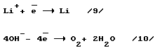
Step 6.
Production of hydrogen and: an aqueous solution of LiOH
reaction equation
2Li + 2H 2 O -> H 2 + 2LiON (3).
Step 7. Cooling the reaction products by absorption chiller.
The absorption chiller is designed for utilization of heat generated by a chemical reaction between the alkali metals Li, Na and water.
The thermal effect of the reaction of
2Li + 2H 2 O -> H 2 + 2LiON + 484 kJ / mol (9, p.248)
Stage 8.
The cleaning liquor filtration.
For continuous processing of seawater special machines developed in the process described above:
- Ion separator and industrial power dividers ions;
- Separator cations and anions from the hydration shell of the converter and the electric charges on the ions (separator-converter);
- Hydrogen generator;
- Modernized absorption chiller;
- Fractional divider.
1. Separator ions and industrial power dividers ions.
Figure 1 is a diagram of ions and the separator block diagram industrial separators ions.
Note: on the sheets with drawings of figures of the text title of the invention is reduced to "A device for continuous processing of sea water ..."
FIG. 1. Schematic diagram of the separator of ions and ion separators industrial unit.
1 - ion separator; 2 - the first section or section prior magnetization of sea water; 3 - the coil of the electromagnet; 4 - section and the second section separating ions; 5 - tube for output anolyte; 6 - the yoke of the electromagnet; 7 - entrance slit for the passage of anions; 8 - tube for output of desalinated water; 9 - the coil of the electromagnet; 10 - the iron core of the electromagnet; 11 - entrance slit for the passage of cations; 12 - tube for output catholyte; 13 - Industrial block delimiters ions; 14 - from the magnetic radiation protection; 15 - the case; 16 - pipeline gathering anolyte; 17 - pipeline supply desalinated water; 18 - pipeline, collecting desalinated water; 19 - fitting for removal of desalinated water; 20 - lad to remove the anolyte; 21 - pipeline that distributes seawater by ion separators; 22 - pipeline gathering catholyte; 23 - tangential entry of sea water in the ion separator.
The separator is designed to separate ions of sea water under the influence of a magnetic field into three fractions: anolyte - demineralized water - catholyte.
Separator ions is a conduit disposed in the magnetic field, and further comprises a pre-magnetization of the water section of a circular magnetic field generated by the coil of an electromagnet equipped with a device for the tangential entry of water, and the separation section of pre-magnetized water by a magnetic field with a magnetic flux perpendicular to the direction of movement of water It is formed as a central pipe, through which slit the diameter of the two smaller diameter conduit connected to output anolyte and catholyte.
PRINCIPLE OF THE FIRST SECTION
In the inlet 23 (Figure 1) is fed tangentially sea water with a salt concentration of 3.5 wt.%. Then 3.5% 3.5% cations and anions / with respect to monovalent metals) will be formed during dissociation 3.5% salt.
When the water flow flows flowing in a turbulent regime, it intersects the magnetic lines of force generated by the solenoid. Thus, as shown in (I, pp. 47-50, 58), electrodynamic movement of ions in a magnetic field gives rise to a magnetic field microwhirlwinds coverage area, which leads to mikroturbulizatsii system and as a consequence of this phenomenon increases the concentration of ions near the conduit walls , resulting in density nonuniformity in the flow (flow in the middle density is less than that of the pipeline wall).
Increasing the residence time of the flow in the magnetic field leads to the fact that the central part of the ion flow occurs becomes smaller and their concentration in the transition layer existing between laminar and turbulent flow movements in the pipeline.
Thus, the magnetized seawater stream exiting the preliminary magnetization seawater section and then entering the separation zone seawater with anolyte - demineralized water - catholyte has at the area of the circle (the cross section YY 1) heterogeneous structure:
- The bulk of the ions (cations and anions) is grouped in the hydrodynamic boundary layer turbulent flow, i.e. at the inner surface of the pipeline, the resulting ion concentration is increased to 17.5% in the surface layer (as calculated), and the ions move along with the flow in one direction (1, c.4);
- A central part of the minimum content of the ion flux, because most of the ions moved to the inner wall of the pipe due to the combined action of the turbulent flow and the magnetic field microwhirlwinds.
The total ion concentration at the outlet of the first section to the total volume remains unchanged, but increases at the inner wall of the pipeline.
PRINCIPLE OF THE SECOND SECTION
The basis of the second section of the separator on the principle of separation of ions of opposite charges in a conductor moving perpendicularly to the magnetic flux (this is exactly what happens in the electrical generators). The theory of this process is given in (2 s.140-142).
The role of metal ions separator performs pre-magnetized conductor electrolyte (sea water), which moves between the two poles of the second magnet (see FIG. 1) perpendicular to the magnetic flux and crossing it, which leads to the separation of ions in different directions, ie . negative ions will move to the left, positive - to the right.
Since ions exiting from the first section of the flow are at the inner surface of the pipeline, the flow cross-section will be of a circular ring (see. Incisions YY and B in Figure 1), which are located on the periphery of the ions, and in the central part of the ring - desalinated water. In these conditions, due to combined effects of the turbulent flow and the magnetic field in the second section microwhirlwinds separator ions will be easier to split the ions in a narrow zone at the inner wall of the pipe, and to transmit according to their electrical charge into the corresponding slots 7 and 11.
The lateral pipes 12 and the separator 5 is no magnetic field the ions, so the ions included in the side tube exit back are prevented and the flow of ions are removed from the separator to the appropriate process apparatus. The concentration of cations and anions at the outlet of the ion separator is 17.5% respectively.
For industrial purposes ion separator 10, discussed above, are combined in block ion separators, as shown in Figure 1. Then the performance of a single block delimiters ions reach
80 x 10 = 800 t / h of demineralized water,
where 80 - Performance of splitter ions per hour.
2. Separator cations and anions from the hydration shell of the converter and the electric charges on the ions (separator-converter).
The process of separation with ion hydration shell is carried out in the unit - separator cations and anions from the hydration shell, combined with a converter of electric charges on the ions.
Figure 2 shows a separator-converter.
FIG. 2. Separator-converter: 24 - separator-converter; 25 - a schematic diagram of the installation for the supply to the conical mesh 40 and 48 high voltage DC; 26 - Voltage Regulator; 27 - step-up transformer; 28 - high-voltage rectifier; 29 - colonized electrode; 30 - collecting electrodes; 31 - ionizer; 32 - high-voltage input and output to the net positive charge; 33 - fitting for entering vapor catholyte; 34 - fitting for entering vapor anolyte; 35 - high-voltage input and output to the net negative charge; 36 - heat-insulating separator body-converter; 37 - quencher pair speed (ve) included in the machine; 38 - nozzle; 39 - slip ring for removing and applying a positive charge to the grid on the collecting electrodes of the ionizer; 40 - Net carrying a positive electric charge; 41 - guide cylinder (a cylindrical grid carrying a positive electric charge); 42 - a protective casing; 43 - slip ring for applying a positive electrical charge on the grid separator cations with high voltage rectifier; 44 - mounting platform; 45 - funnel for a couple directions to the absorption chiller; 46 - a protective casing; 47 - guide cylinder (a cylindrical mesh carrying an electrical charge); 48 - Net carrying a negative electric charge; 49 - slip ring for the removal of the grid and supply a negative electric charge on the discharge electrode of the ionizer; 50 - receiver pair, passed through the mesh; 51 - nozzle; 52 - quencher pair speed (anolyte) included in the machine; 53 - slip ring for supplying negative electric charge on the grid separator anions from the high-voltage rectifier; 54 and 55 - connections for input and output of a heat exchanger chilled and heated water; 56 - outlet for removing oxygen; 57 - outlet for condensate; 58 - the heat exchanger; 59 - steam-gas pipe to input (oxygen + water vapor) mixture to the heat exchanger; 60 - the spherical electrode; 61 - DC generator of low voltage; 62 - outlet for discharging steam to the absorption chiller; 63 - plating bath: 64 - outlet for discharging molten lithium; 65 - the pump for supplying molten lithium in the hydrogen generator; 66 - outlet for discharging molten lithium.
Converter-separator for separating the hydrate shell of cations and anions, and neutralizing the electrical charge on them to obtain a lithium metal, oxygen and reaction water.
Separator-converter is a system, which includes
1. Installation for supplying high voltage DC on the conical mesh separator cations and anions from the hydration shell.
2. Separator cations and anions from the hydration shell, ie, apparatus for cations and anions.
3. Neutralizer electrical charges on cations and anions, i.e. obtaining target products Li, O 2 and H 2 O, including low-voltage direct current generator.
1. Installation for supplying high voltage DC on the conical mesh separator cations and anions from the hydration shell.
This unit is designed to create a bevel on the grids of high electric field strength that can repel the charged grid like charges, located on the cationic or anionic, ie, this field are repelled by grid cations or anions, respectively, but passes through the mesh steam.
The basis for the creation of the installation is a unit AF-90-200, designed to clean gas from impurities on a commercial scale.
This unit has a maximum voltage of 90,000 V and a nominal current of 200 mA transformer secondary winding (8, s.742). The circuit shown in Figure 2.
The study is based on the principle of electrical installations gas cleaning (4 s.251-255), but it made the following change:
- A continuous flow of purified gas moving in the positive and negative charges on the discharge and collecting electrodes, undergoes ionization as described in (4 s.251-255), here we use the inert gas, argon Ar ionization potential with 15.755 eV according to reaction 0 Ar -> Ar + (14, c.250).
- The inert gas is in a closed volume, i.e. in a sealed bottle.
The principle of the installation work (see FIG. 2).
With the help of the voltage regulator 26, booster transformer 27, a high voltage transformer 28 on the discharge electrode 29 and collecting electrodes 30, are in the ionizer 31, a high voltage DC 90000, and in the power of 200 mA of current. As a result, there is a "crown" between the discharge and collecting electrodes. In the event of "crown" in an airtight cylinder of the ionizer 31 are ionized rarefied gas of Ar and with the electrons and positively charged cations of Ar +, under the influence of an electric field of positively charged cations of Ar + will move the discharge electrode and neutralize it, and the negatively charged electrons will move to the collecting electrode and and neutralize it. As a result, Ar gas ionization external electric circuit is closed and electrical current is movement of the entire chain. Thus on the conical grid 40, the positive "+" electric charge, and a conical mesh 48 - negative "-" electrical charge.
2. Separator cations and anions from the hydration shell, ie, apparatus for cations and anions.
Separator cations and anions from the hydration shell (abbreviated - separator) designed for cations and anions, bearing the electric charge (Li + and OH -), and their subsequent submission to the converter of electric charges on the ions.
PRINCIPLE stripper
For normal operation of the separator of ions from the hydration shell in the first place must be observed the following:
- If couples catholyte or anolyte supplied inside the conical nets 40 and 48 directly from the hydrogen generator, the part of the couple catholyte or anolyte, having a high speed downstream (P = 10 6 Pa, T = 472 K), slip the mesh cone and are paired ions will not be released from the hydrated membrane and enter into the guide cylinders 41 and 47 and further to the converter, where the steam enters into chemical reaction with the formed Li, and this premature reaction and it can not be allowed. At breakthrough vapor anolyte from some parts of the anolyte is not formed by ion of OH -, causing side reactions to a spherical electrode, which is not desirable. Only one way out - to slow entering the steam separator catholyte and anolyte to a minimum, ie, speed up the passage of the steam through the grid and joining the pair in a pair of receiver 50. The steam rate can adjust the speed at which the condensation in the heat exchanger of the absorption refrigeration machine where steam from the receiver 50 is fed to a further process cycle - the system must be supported by a permanent solution, which is formed by condensation steam on the cold wall of the heat exchanger in an absorption chiller.
Process is as follows
From the hydrogen generator (see Fig. 3), the separator serves to different pipelines vaporous catholyte and anolyte with a temperature of 473 K, respectively, to the nozzles 33 and 34. Further, steam is divided into two equal parts and is supplied in spray nozzles 38 and 51 from quencher pair are in the speed 37 and 52. the jet of steam nozzles additionally sprayed into many tiny streams, thereby increasing the area of the collision of two jets of steam, with the same energy. In a collision of both flow velocity is damped to the optimum value, ie, steam velocity to pass through the conical mesh 40 and 48 to the cold heat exchanger grid in an absorption refrigerating machine.
By the vacuum produced by condensation of steam vapor catholyte or anolyte, respectively, from the interior of conical mesh rushes through the mesh cell 40 or 48 to couple the receiver 50 and from there through the pipe 62 to the heat exchanger of the absorption chiller (see. FIG. 4) where the steam condenses and condensate water is directed back into the production cycle.
The positive electric charge on the whole surface of the grid 40 and the negative electric charge on the grid 48 does not react with water vapor, which is an insulator, and therefore steam flows freely through the grid, and cations such as Li +, due to the high temperature of 473 K and a pressure of 10 6 Pa while without the hydration shell, coming to the net, having a positively charged electric field repel Li + cation to the center of the cone-shaped nets, because like charges repel each other, but simultaneously, with the movement of the cations toward the center of the conical grid they move down to the negatively charged electrode (molten lithium on which an electric current flows), as unlike charges attract each other. Cations or anions exist only in high-voltage electric field under vacuum.
On leaving the conical mesh concentrated Li + cations in the cationic circular beam by the electric field of high voltage, includes a guide cylinder and then a cationic beam falling continuously on the molten lithium, carrying an electric current, ie electrons, due to which there is a reaction, and ![]() .
.
Similarly, it is the process by an ion ![]()
The neutralization of the electric charges on the ions and is a continuation of phase 4, held in the unit-separator cations and anions from the hydration shell, combined with a converter of electric charges on the ions (see FIG. 2).
The process of neutralization of electric charges held in the converter, which is the third component of the unit - separator cations and anions from the hydration shell.
Neutralizer designed for instant electrochemical reactions with ions, such as Li + and OH -.
The neutralizer is a system consisting of a DC low voltage generator 61 and the outer part of the generator circuit, which includes
- A metal ball contact 60;
- Track 63 of molten lithium;
- Guide cylinder 47 to supply the contact ion Li +;
- Guide cylinder 60 to supply the contact ion OH -;
- A heat exchanger 58 for cooling the O 2 and H 2 O vapor;
- A pump 65 for pumping molten lithium in the hydrogen generator.
From the diagram described above it is evident that flowing in the converter process - is not electrolysis process, as no electrolyte, and hence no movement of the ion generator electrolyte through an external circuit. It is a process of neutralization of electrically charged particles, which occurs due to the impact of joining the anion and cation of electrons, ie, going interion transfer electrons from anions, cations, and the anion is oxidized, and the cation is restored.
The operating principle of converter (circuit of Figure 2).
When neutralizing the electrical charges on cations and anions it is carried out the principle of inter-ion electron transfer from anion to cation by an external circuit generator 61 VDC (abbreviated - the generator).
This principle to consider reactions (9) and (10).
According to reaction (10) by oxidation four hydroxides OH - generated O 2 and H 2 O and exempt ![]()
![]()
According to reaction (9) for the restoration of the four lithium cations Li + required ![]()
![]()
Thus, when co-host reactions (9) and (10) has a complete balance on the electrons, ie, four electrons freed by the reaction (10) and four electrons is expended to conduct reaction (9).
TECHNICAL this issue is resolved FOLLOWS
In the external oscillator circuit 61 connects the contact ball 60, which passes the reaction (10).
To touch on the ball 60 has passed the reaction (10) must be continuously withdrawn electrons are isolated on a spherical contact 60 can randomly run off the ball contacts 60 in all directions. This can not be allowed. Therefore, after the ball contact 60 carrying an electric current produced by the generator of direct current with the strict direction of motion of the electrons from the clamp "+" to the terminal "-" of the external circuit of the DC generator. Electrons emanating generator "entrain" and electrons for an obtained at passage 60 at the contact of the reaction (10).
Thus, for electrons formed by the generator 61 in an amount of Q 1 and flowing through the inner and outer generator circuits, further to contact the external circuit 60 "pouring" the electrons formed by the reaction of (10) in an amount of Q 2.
The total number of electrons flowing through the external circuit after the contact 60 is equal to Q 1 + Q 2. This is the number of electrons generated by the generator direction of motion of the electrons in the outer and inner circuits (from "+" to "-"), and shall go in this direction, on the other can not be.
Electrons reaching the contact 63 in an amount of Q 1 + Q 2, react (9) for conducting electrons which is consumed in an amount of Q 2, and thus will be observed conservation of energy and mass.
The remaining contact 63 after passing electrons in an amount of Q 1 received through the clip "-" back to the generator internal circuit and begins the cycle repetition.
Contact 63 is a bath of molten lithium on which an electric current flows, that is, electrons. Restore cation Li + becomes a lithium atom and then melts. With the accumulation of molten lithium, he appears out of the bath.
From the above it follows that the DC generator 61 is a carrier of electrons from the reaction (10) to the reaction (9). The reaction products of O 2 and H 2 O via a conduit 59 and heat exchanger 56 are derived from the converter:
- Oxygen compressor station;
- The water is recycled.
In this process, an external source of energy is only a DC generator 61 which provides the direction of movement of the electrons obtained by the reaction (10).
3. The hydrogen generator.
3 is a schematic of a hydrogen generator.
3. Driving the hydrogen generator: 67 - Hydrogen Generator for the first production line, working on lithium metal; 68 - fitting for vapor withdrawal to a set temperature of the catholyte; 69 - fitting for the withdrawal of anolyte at a predetermined temperature; 70 - heat-insulating body of the hydrogen generator; 71 - partition (two) separates the anolyte from the catholyte in the annulus of the reaction zone; 72 - feeder ring hydrogen generator (condensate + desalinated water); 73 - nozzle; 74 - pipeline for supplying the reagent (water or molten lithium) in the nozzle; 75 - molten lithium distributor for the nozzles; 76 - theoretical trajectory spray water nozzles or molten lithium; 77 - reaction zone; 78 - feeder ring with molten lithium hydrogen generator; 79 - fitting for entering the anolyte into the annulus of the reaction zone; 80 - zone cooling of the reaction products; 81 - the heat exchanger; 82 - the pipeline for removal of hydrogen; 83 - outlet for removing the aqueous LiOH solution; 84 - Two pipe to enter the cold coolant; 85 - connection for the withdrawal of the heated coolant; 86 - fitting for the input of catholyte into the annulus of the reaction zone; 87 - inlet for introducing the molten lithium feeder ring; 88 - water dispenser according nozzles; 89 - fitting for introducing water into the annular feeder; 90 - electric heater catholyte vapor to a predetermined temperature; 91 - electric heater anolyte vapor to a predetermined temperature.
Hydrogen generator for producing hydrogen according to the reaction (3):
2Li + 2H 2 O -> H 2 + 2LiON (3).
Reaction of alkali or alkaline earth metals with water is carried out in a heterogeneous phase.
If the process is carried out in a heterogeneous system between the reagents are in different phases, the reaction is carried out at the interface. Then the number of reaction events not related to unit volume and unit surface and the dimension w (reaction rate) is measured as mol / s · cm 2. Examples of such reactions can be many combustion processes the solids medium in gaseous oxidant (O 2, Cl 2, etc.) or by the action of water on the active metal (6, s.205-206).
It follows that to create high speed of reaction (3) it is necessary to create a large surface in the molten lithium and water introduced into the reaction zone.
As this question is solved below.
The hydrogen generator is
1. The reaction chamber 77, the chilled catholyte and anolyte. It takes the interaction with lithium for reactions with water (3). Due to the reaction heat and electric heaters 90 and 91 of the catholyte and anolyte to evaporate and the temperature 473 K and a pressure of 10 6 Pa ions are directed from the separator for the hydration shell of the ions (step 4).
2. The cooling zone of the reaction products, where the heat exchangers 81, cooled by cold water, the reaction products are cooled to a temperature of 373 K.
3. The density of saturated water vapor equal to 0.5977 g / l (at 100 o C and 1 atm) (see 8, s.607.); hydrogen density of 0.0899 g / l (at 0 o C and 1 atm) (sm.8, 620.); Hydrogen 7 times lighter than water vapor (0.5977: 0.0899 = 7), so it will be easily separated from the steam and condensate in the conduit 82 to leave.
4. Hydrogen and easily separates from the aqueous solution of LiOH and the conduit 82 is discharged from the hydrogen generator.
5. The alkaline solution is directed through pipe 83 to a centrifuge for separating solid impurities, i.e. wastewater treatment filtration is carried out.
The principle of operation of the hydrogen generator is as follows.
At eighteen nozzles 73 at the same time served
- 9 nozzles molten lithium from step 5;
- Water nozzles 9 (condensate and demineralized water) and with 1 step 7.
Due to increased pressure in liquid supply nozzles occurs twisting fluid at the nozzles and outlet nozzles spraying lithium and water into tiny droplets which, moving toward each other and collide instantaneously react with each other (Li 2 O), forming a reaction according to (3) of lithium hydroxide and hydrogen.
Due to the thermal effect of the reaction, the unreacted water is converted into steam.
Excess heat left after heating the catholyte and anolyte is withdrawn from reaction zone 77 into heat exchangers 81. The heat exchanger tubes flowing water, chilled to +1 o C. The heated heat transfer fluid in vapor form through the pipe 85 is welded to an absorption chiller to provide cooling needed for the conduct of the process.
Define how many times the hydrogen is diluted by water vapor in the hydrogen generator. (Conditionally make payment without reduction to normal conditions).
1. The amount of hydrogen, which is obtained from 14 kg of Li according to reaction (3) -22,400 m 3 of hydrogen (see. Material calculation).
2. In the evaporation 18 g of H 2 O generated 22.4 liters of water vapor, while in terms of the m-mol obtain
18 m-mole - 22400 m 3 of steam
295 m-mol - x
x = 367111 m 3 of water vapor.
Dilution with water vapor of hydrogen in the hydrogen generator will be
367 111: 22400 = 16.4 times.
Thus, when the hydrogen dilution water vapor 16.4 times exclude the possibility of explosion of hydrogen in the hydrogen generator.
The nozzle 73 is a nozzle with a continuous spray cone (10, p. 77), it is used in cases where full coverage requires a certain surface, and preferably have a uniform distribution of the drops.
The diameter of the outlet nozzles 0.5-50 mm, productivity 0,04-750 l / min.
4. Upgraded absorption chiller.
The reaction heat can be taken away by cooling the reaction mixture with water from the pond. But the water consumption would be enormous, and, in addition, the ambient temperature change.
The most expedient to cool the reaction mixture is the use of an absorption chiller, where almost all of the extracted heat is absorbed by the hydrogen generator of the absorption machine for production of cold and isolation of vodnoammiachnogo ammonia solution.
4 is a diagram of the absorption upgraded machine.
FIG. 4. Driving upgraded absorption chiller: 92 - absorption chiller; 93 - the generator to evaporate vodnoammiachnogo good solution; 94 - capacitor; 95 - a throttle valve; 96 - evaporator; 97 - a branch pipe to drain the chilled water to the heat exchanger of the hydrogen generator; 98 - absorber; 99 - a throttle valve; 100 - heat exchanger; 101 - pump; 102 - condensate distributor; 103 - pump for the condensate to the evaporator to cool; 104 - condensate pump for feeding a hydrogen generator; 105 - connection for condensate drain in the hydrogen generator; 106 - sleeve for input steam coming from the heat exchanger of the hydrogen generator; 107 - tube steam input coming from the trap ions by hydration shell.
Upgraded absorption refrigerating machine is designed for withdrawal of heat from the reaction to produce hydrogen in a hydrogen generator and is as follows.
Generator 93 (Figure 4) is used to vaporize the good vodnoammiachnogo solution - is produced following modernization.
As the coolant used to vaporize the ammonia vapor entering the heat exchanger 106 from the hydrogen generator (3), and steam from the separator ion (FIG. 2). Formed after the heat exchange in the absorption condensate is sent to the machine in the appropriate amounts in a hydrogen generator for producing hydrogen reacting further condensation in the evaporator 96 is cooled to approximately +1 o C and cooling water heat exchanger 106 is directed to a hydrogen generator for withdrawal of heat from the reaction mass, m. e. water on the circuit passes a closed cycle without leaving the absorption machine.
Included in the machine circuit capacitor 94, throttling valves 95 and 99, an evaporator 96, an absorber 98, a pump 101, a heat exchanger 100 are not subjected to modernization.
The basic principle of the absorption machine is modernized working principle taken from (5, p.213) and (11, s.441).
Gaseous ammonia (~ 95% NH 3) vodnoammiachnogo released from solution in the generator 93 (12, 11 and s.429, s.441) at a high pressure of about 10 6 Pa (10 atm) and a temperature of 383 K enters the condenser 94, where it is condensed, giving heat to the cooling water Q. Liquid ammonia at P = 10 6 Pa and T = 298 K passes a throttling valve 95 and is evaporated in the evaporator 96, sensing heat at a low temperature level T 0 of the condensate, and cooled to a temperature of +1 o C condensate is directed through the pipe 97 in the pipe 84 a hydrogen generator to a heat exchanger 106. After ammonia gas evaporator with T = 253 K (-20 o C) and a pressure of P = 1,17 · 10 5 Pa (1.2 atm) is directed into the absorber 98 and cooling (heat removal dissolution) absorbed water to form a highly concentrated solution (~50% NH 3). The resulting solution is pumped by pump 101 through heat exchanger 100 to the generator 98. The generator 93 by heating with steam (supply of heat of evaporation) entering through nozzles 106 and 107 respectively of the heat exchanger and a generator of hydrogen ions from the trap hydration shell, most of the ammonia evaporates and in the form of gas enters the condenser 94 depleted water-ammonia solution (~ 20% NH 3) leaves the generator 93 through the heat exchanger 100 and the throttle valve 99 to the absorber 98 where again concentrated to ~ 50% due to the absorption of ammonia gas and sent to the generator 93 recycled.
5. The fractional divider.
Figure 5 is a fractional divider circuit.
5. Fractional separator: 108 - fractional divider; 109 - connection for downloading sludge; 110 - turbine stirrer fitted with a reducer and a special mechanism for raising and lowering the agitator: a) at position stirrer particle settling; b) suspending stirrer particles in position; 111 - the level of suspension of polymetallic conglomerate; 112 - valve; 113 - valve; 114 - spout; 115 - catch; 116 - conduit for draining the suspension of Ca (OH) 2 sump; 117 - catch; 118 - connection for the Gulf of desalinated water from the bottom up in the fractional divider; 119 - pipe for draining the suspension polymetallic conglomerate into the sump; 120 - catch; 121 - conduit for directing suspension polymetallic conglomerate into the sump; 122 - conduit for directing suspension of Mg (OH) 2 into the sump; 123 - catch; 124 - spout; 125 - valve; 126 - pipe to drain water; 127 - catch; 128 - spout.
Process Theory fractional separation of solid particles is given in step 15.
The fractional divider is designed
- To separate the slurry into the conglomerate polymetallic demineralized water into three fractions:
a fraction of a slurry of Ca (OH) 2;
fraction suspension Mg (OH) 2 + Al (OH) 3 (as mikrosmes);
a fraction of the slurry remaining compounds within the polymetallic conglomerate;
- Separation of fractions separated from each other.
The fractional divider is a column with a diameter of 2 meters and 65 meters in height ~ in which on the basis of Stokes law are separated according to their particle diameter and density.
WORKING PRINCIPLE Fractional Separator
The fractional divider 118 is filled through a nozzle demineralized water for about 2 meters above the valve shaft 112, after which valve 112, 113 and 125 from a vertical position (relative to the plane of the dampers) are transferred to the horizontal.
Through conduit 109 is loaded in the upper part of the sludge separator, which is supplied from the centrifuge of step 13 in an amount equal to three-hour operation of the hydrogen generator.
110 includes a turbine agitator, and valves 112, 113 and 125 are transferred from a horizontal position to a vertical, whereby sludge and demineralized water are transferred into a suspension.
Disconnected turbine agitator 110 and valve 112, 113 and 125 are transferred from a horizontal position to an upright, whereupon polymetal conglomerate particles that are suspended in the water or under the influence of gravity fall down.
After 2 chasa flaps 112, 113 and 125 is transferred from horizontal to vertical position.
For particles chasa 2 Ca (OH) 2 and Al (OH) 3 are lowered down the pipe to 42.24 m and 54.72 m, respectively, the compounds heavier particles for deposition chasa 2 pass path from 87.84 to 709 m ,2 meters. However, their descent stops when the damper passage 125 where the particles accumulate at the nozzle 11.
Install shutters on the upper casing lid parting separator:
- Damper 112 - 2.5 meters;
- Damper 113 - 51 meters;
- Damper 125 - 55 meters;
- Lower connector housing is set at around 55 meters.
After installing the dampers are opened to a horizontal position valves 115, 120 and 127, and split into fractions slurry is directed into the intermediate container.
Since fraction slurry remaining metal hydroxides and metal based on metals together weigh only ~ 24 kg, they were collected in a single collection of powder on the bottom of the fractional divider of several separation processes, and then opens the valve 120 and the entire fraction is sent to an intermediate tank . From the intermediate fractions separate containers slurry fed to the centrifuge.
Fugato desalinated water is sent to the discharge channel for the desalinated water for further use, and sludge (sludge) for further processing at the step 16.
- LIST OF FIGURES AND DRAWINGS AND OTHER MATERIALS -
The first line for RECEIVABLE demineralized water, hydrogen and oxygen
6 is a diagram of the first production line.
FIG. 6. Scheme of the first production line for the production of desalinated water, hydrogen and oxygen: 13 - industrial block delimiters ions; 16 - connection for the withdrawal of anolyte; 19 - fitting for removal of desalinated water; 20 - outlet for removing catholyte; 21 - connection for entering into an industrial unit 13 separators ions of sea water; 24 - Separator-converter; 33 - fitting for entering vapor catholyte; 34 - fitting for entering vapor anolyte; 40 - Net carrying a positive electric charge; 48 - Net carrying a negative electric charge; 56 - outlet for removing oxygen; 57 - a branch pipe for condensate (water of reaction); 62 - outlet for discharging steam to the absorption machine; 66 - outlet for discharging molten lithium; 67 - Hydrogen Generator; 68 - fitting for vapor withdrawal to a set temperature of the catholyte; 69 - fitting for the withdrawal of vaporized anolyte at a predetermined temperature; 79 - fitting for entering the anolyte into the annulus; 82 - outlet for removing hydrogen; 83 - outlet for removing the aqueous LiOH solution; 84 - Two pipe (both sides) to enter the cold coolant; 85 - connection for the withdrawal of the heated coolant; 86 - fitting for the input of catholyte into the annulus; 87 - fitting for entering molten lithium; 89 - fitting for the input of desalinated water in the feeder ring; 97 - fitting for the withdrawal of cold water from the absorption chiller and feed it through the outlet 84 is recycled; 105 - connection for condensate drain in the hydrogen generator; 106 - sleeve for input steam coming from the heat exchanger of the hydrogen generator; 107 - sleeve for input pair supplied from converter-separator; 129 - second separator ions dividing LiOH solution on the anolyte and catholyte; 130 - sleeve for the filtered input LiOH solution; 131 - connection for the withdrawal of anolyte with its direction in the pipe 79 of the hydrogen generator; 132 - connection for output catholyte with its direction in the pipe 86 of the hydrogen generator; 133 - gas tank for oxygen; 135 - a mixer for mixing the condensate with demineralized water coming from the separator unit 13 ions; 134 - mixer for mixing with steam condensate; 136 - centrifuge; 137 - sleeve for LiOH solution filtered output; 138 - connection for the withdrawal of sludge; 139 - gas tank for hydrogen; 140 - body of water; 141 - filter intake; 142 - pump; 143 - anolyte outlet conduit; 144 - the pipeline for discharging the catholyte; 145 - mixing anolyte and catholyte; 146 - a spray mixture of anolyte and catholyte in the pond.
The first production line is designed to produce desalinated water from sea water, hydrogen and oxygen.
The first production line is an engineering construction, which is based on unparalleled high-speed machines for the processing of sea water up to the desired products: demineralized water, hydrogen and oxygen.
PRINCIPLE OF THE FIRST LINE TECHNOLOGY
From the reservoir 140 through the intake-filter 141 by a pump 142 sea water through the pipe 21 is supplied to the industrial unit 13 ion separators, where sea water is divided into fractions: anolyte - demineralized water - catholyte. Demineralized water is supplied through pipe 19 into mixer 135, where there is a mixture of demineralized water and condensate which comes from the absorption chiller 92 and is directed through pipe 89 to a hydrogen generator 67.
The anolyte and catholyte of the industrial unit 13 separators ions directed via conduits 143 and 144, respectively, on the second processing line or via the mixer 145 and dispenser 146 back into the reservoir 140.
Hydrogen generator 67 - the central unit, in which all the main flock material flows involved in hydrogen generation, and extending therefrom material flows involved in obtaining Li, O 2 and water of reaction.
The hydrogen generator through the tubes 89 and 87 (Figure 6) to the nozzles 18 simultaneously fed (by calculation) demineralized water plus condensate (they are fed from a commercial ion separator unit 13 and the absorption refrigerating machine 92) and the cycle goes from the molten lithium catalyst separator 24. The injector of lithium and water is sprayed into small droplets, creating a huge contact area between lithium and water.
Under these conditions, water passes interaction of lithium and reaction to produce hydrogen and an aqueous LiOH solution are discharged from the hydrogen generator 67 via the pipes 82 and 83 respectively. Hydrogen through the pipe 82 is sent to the gas tank 139.
The reaction of the lithium reaction with water has a large thermal effect, equal to 484.9 kJ mol -1.
In the set operation in the hydrogen generator is allocated per hour 969 800 000 kJ of heat, which is given coolants, namely
- Anolyte and catholyte, which is heated to a temperature of 473 K;
- Cold water, which is supplied with a temperature of 274 K;
- The heat is spent on evaporation of ammonia from the strong vodnoammiachnogo solution in an absorption chiller.
Vaporous anolyte and catholyte, heated to a temperature of 473 K, routed through tubes 64 and 68 in the converter-separator 24 to produce ions Li + and OH - which carry the positive and negative charges, respectively.
The converter charges the ions are neutralized to form the Li, O 2 and H 2 O.
Li in the molten state through nozzles 66 and 87 directed in the hydrogen generator is recycled, and oxygen through the pipe 56 - 133 in the gasholder.
The reaction of oxygen in obtaining water as the condensate is fed into a hydrogen generator 67 through the pipe 57 and the mixers 134 and 135 is recycled.
Water vapor after separating it from the ions ( "+" and "-") in the separator-converter 24 and the steam was in the hydrogen generator is supplied to the absorption machine 92 via the pipes 107 m 106, respectively, to their heat for evaporation ammmika of strong vodnoammiachnogo solution. Further, the condensed water vapor is fed as a condensate in the hydrogen generator is recycled (flow conducted through manifold 105, a mixer 134, conduit 135 and conduit 89).
Withdrawal of heat from the reaction is as follows: cold water through the pipe 97 and pipe 84 to heat exchanger 81 (see Figure 3.) Of the hydrogen generator, wherein the reaction by taking away the heat exchanger trubax water evaporates and steam through the pipe 85 and pipe 106 It enters the absorption chiller 93 to the evaporation of ammonia from the solution vodnoammiachnogo. The condensed vapor as a condensate through condensate valve 102 (Figure 5) is sent to the evaporator 96, where it is cooled to a temperature of +1 o C and is directed through pipe 97 to the hydrogen generator is recycled.
The resulting reaction LiOH aqueous solution through pipe 83 flows into a centrifuge 136 where the aqueous LiOH solution was filtered from possible solid impurities, then through the nozzles 137 and 130 in the second solution enters the ion separator 129. The aqueous solution of LiOH is divided into anolyte and catholyte, is sent to the hydrogen generator is recycled withdrawal reaction heat from the reaction zone of a hydrogen generator.
Anolyte through pipes 131 and 79 goes to the tube space of the reaction zone of the hydrogen generator.
Tube space is divided by partitions into two parts for the anolyte and catholyte.
The catholyte through pipes 132 and 86 enters the second half of the annulus of the reaction zone of a hydrogen generator.
With the arrival of the anolyte and catholyte in the hydrogen generator of the second separator ions begins recycle operation.
Thus, consideration of the first production line scheme shows that the material flows continuously moving, each in its own loop, and the lithium from the process cycle is output, and continuously circulates from one device to another in the form of Li, Li + or LiOH process step, respectively.
The process is continuously added to demineralized water, walking on the formation of hydrogen and oxygen, are continuously discharged from the process line.
Extract from seawater cations and anions, and their translation into the respective metal atoms and gases (H 2, O 2, Cl 2, Br 2, I 2, F 2, SO 3).
Extraction of seawater contained therein metal salt carried on the second processing line for processing of sea water according to the following steps:
Stage 9.
Preparation of cations and anions containing no shell in the hydrate-converter separator.
Stage 10. Neutralization of electrical charges on the ions that do not contain hydration shell to form the desired products.
Stage 11. Separating the gas mixture.
Step 12. Preparation of hydrogen by reaction with an alkali melt water.
Stage 13. Centrifugation of the suspension liquor.
Stage 14. Translation metal hydroxides (N 2, K, Li, Rb, Cs ) to halides, sulfates, and carbonates of these metals.
Stage 15.
Fractional separation suspension polymetallic conglomerate into three fractions:
- Fraction hydroxide Ca (OH) 2;
- Fraction of Mg (OH) 2 and Al (OH) 3;
- A fraction of the remaining metal hydroxides and individual metals.
Stage 16. Processing of Ca (OH) 2, Mg (OH) 2 and the rest of the polymetallic conglomerate.
DESCRIPTION OF STAGES
Step 9. Preparation of cations and anions, non-hydrated membrane in the separator-converter.
The theoretical basis of this process is given above in step 4. The process takes place in a separator unit-converter (2).
Consider which electrochemical processes take place in the preparation of cation containing no hydration shell.
The bottom of sea salt contains 77,7% NaCl, ie, NaCl is the basis of salts contained in seawater. To further simplify the calculations, we assume that all the cations contained in seawater are conventionally cation Na +, and the error in the calculation would be indicative admissible for this type of calculation.
Let us consider the processes occurring during the ions from the water compartment, ie producing ions containing no hydration shell.
I. Branch metal cations of the water passes through two phases:
a) heating of the catholyte (cations + water)
The catholyte 
Heating of the catholyte takes place in two steps
- Pre-heating stage 14 in a mixer-reactor by the heat of dissolution of gas in the water and the chemical reactions (24-30);
- Final heat stage 12 occurs in the hydrogen generator by the heat of reaction for producing hydrogen from water and sodium.
b) separating the cation of saturated steam 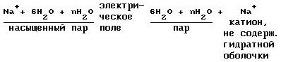
2. Consider the processes taking place in the preparation of anions containing no hydration shell.
and assume that all the anions are conventionally anion Cl -. Anions from water separation takes place in two phases:
a) heating of the anolyte (water + anions)
Anolyte 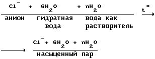
The heating of the anolyte and catholyte like occurs in two stages at 14 and 12.
b) separating the anion of saturated steam: 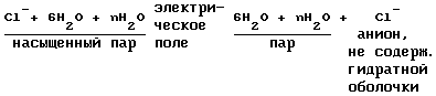
Step 10. Neutralization of electrical charges on the ions to form the desired products.
This process takes place in the separator-converter (2) simultaneously in two directions:
1 - restore cations;
2 - oxidation of anions.
a) reaction of passing cations on the reduction of contact 63 (FIG. 2) consisting of molten sodium (previously lithium) 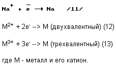
Metallic sodium and potassium with many metals form alloys of various compositions, which are soluble in the molten excess sodium (24). Metals that do not form a sodium and potassium alloys will be in molten sodium in a suspension.
In step 10, obtained by: alkaline metal melt, which comprises all the metals indicated in the table.
b) reacting extending in the oxidation of anions at the ball contact 60 (Figure 2).
Formed on pin 60 a mixture of gases (473 K temperature) is sent to the shop for the separation of the gas mixture.
11. Phase separation of the gas mixture.
The gas mixture contains in its structure Cl 2, Br 2, J 2, F 2, SO 3, CO 2, O 2. According to industry demand a certain part of the gas mixture is separated via control distribution of the total gas mixture, and subjected to fractional separation according to (4 s.750). fractional separation products are sent to customers or used in situ.
The remaining gas mixture is not divided is directed to step 14, in a mixing reactor for the reaction to transfer of metal hydroxides (NaOH, KOH, LiOH, RbOH, CsOH) in chlorides, bromides, iodides, fluorides, carbonates and sulfates in appropriate amounts.
Step 12. Preparation of hydrogen by reaction with an alkali melt water.
From step 10 to step 12, molten metal enters the alkaline hydrogen generator.
At this stage the following reactions:
a) the reaction leading to the formation of hydrogen and water soluble alkali compounds:
2Na + 2 H 2 O -> H 2 + NaOH
NaOH -> Na + + OH - ( 21)
Similarly, reaction with sodium tested with mikoprimesyami K and Li, Rb, Cs;
b) reactions leading to the formation of hydrogen and a water-insoluble polymetallic conglomerate.
With two or trivalent metals which form insoluble or sparingly soluble metal hydroxides in water, reactions take place, e.g.
Mg + 2H 2 O -> H 2 + Mg (OH) 2 (22)
2Al + 6H 2 O -> 3H 2 + Al (OH) 3 (23)
This group of metal hydroxides include: Al, Ba, Fe (II), Fe (III), Y, Ca, Co, Mg, Mn, Cu, Ni, Pb, Sr, La, Ra, Sc, U.
Several below said metals do not react with water and form metal hydroxide and include metals Sr, Ga, Au, Mo, As, Sn, Hg, Se, Ag, Th, Cr, Si, V, Zn.
Thus, all listed in "b" gidrokcidy individual metals and metal (not vctupayuschie reacted with water) make up the so-called "polymetallic conglomerate", ie insoluble in water, the mixture of all the elements included in the table except for the alkali metals. These metal hydroxides with metal walls of the reactor are washed with an alkaline solution and steam, and the resulting slurry together with steam and hydrogen, is sent to heat exchanger 81 (Figure 3), where water vapor is condensed and separated from the hydrogen.
Condensate is an alkaline solution of Na, K, Li, Rb, Cs, which includes a polymetallic conglomerate and after cooling in heat exchanger 81 is directed to the condensate slurry step 13 "Centrifugation of the suspension liquor."
Hydrogen, having passed the heat exchanger 81 (Figure 3), cooled by cold water, is directed to a hydrogen compressor 200 (Figure 8) station.
Step 13. Centrifugation liquor slurry.
At step served liquor suspension containing polymetallic conglomerate. The process is continuous centrifugation, and wherein
- Sludge (polymetallic conglomerate) directed to the fractional divider 103 (5), wherein the conglomerate polymetallic mixed with demineralised water to form a slurry and then separating the resulting slurry into fractions depending on the density of the metal or metal hydroxide particles and size;
- Centrate (liquor) from the centrifuge 178 (7) guided along two lines
a) the stage 14;
b) to control the distribution of 188 (7) and from the central point 214 (9) of the distribution of material flows.
Industrial orders shown a certain part of the alkaline solution, and forwarded to the shop 228 (9) to secede from NaOH and KOH obtain concentrated solutions of NaOH and KOH, and a solid KOH and NaOH. It does not stand out from the solution RbOH, LiOH, CsOH, since content in seawater Rb, Li and Cs in terms of metal was 1.5 × 10 -5 - 2 · 10 -7% (by weight), i.e. a very small amount.
Step 14. Transfer metal hydroxides (Na. K, Li, Rb, Cs) to halides, sulfates, and carbonates of these metals.
As a result of physico-chemical effect on the catholyte and the anolyte obtained
- Hydrogen - is used as the target product as intended (primarily for recovery of metal hydroxides);
- Polymetallic conglomerate - is used as a raw material for chemical and metallurgical plants to obtain from it the desired products;
- A mixture of gases (Cl 2, Br 2, J 2, F 2, SO 3, O 2, CO 2) - the industry will be used only a smaller part of the total amount of gas produced, most of these gases is not used and need to recycle;
- An alkaline solution of metals (Na, K, Li, Rb, Cs) - industry and will use less of the total amount of the resulting alkaline solution, a large part of this solution will not be used and need to recycle;
- A mixture of gases (Cl 2, Br 2, J 2, F 2, SO 3, O 2, CO 2) and an alkali metal solution (Na, K, Li, Rb , Cs), obtained in the process of physical and chemical processes, to leave on the surface in large quantities is impractical because It can happen ecological disaster, so the mixture of gases and alkali metal solution should be transferred to the salt, which is the basis of sea water, such as: NaCl, NaBr, NaJ, NaF , Na 2 SO 4, Na 2 CO 3 and, respectively, K, Li, Rb , Cs, of alkaline solution to a mixture of gases and sent to the mixer-reactor unit 147 (7), and the resulting mixture was poured there into the ocean through a pipe length of about 1 km and with a plurality of small holes along the entire length of the pipeline, which is perpendicular to the sea current on the seabed, which will lead to a gradual recovery of the salt concentration in sea ocean.
Consider the chemical processes by which to complete the task.
I. When dissolved in water is chlorine hydrolysis to form hypochlorous acid ![]()
hypochlorous acid is easily decomposed
NClO -> HXL + 1/2 O 2 (25)
на чем основано белящее и дезинфицирующее действия хлора в присутствии воды.
2. Выделившаяся HCl взаимодействует с NaOH по реакции
NaOH + НCl --> NaCl + H 2 O (26)
аналогичная реакция проходит и с гидрокcидами K, Li, Rb, Cs.
3. Серный ангидрид SO 3 , растворяясь в воде, образует серную кислоту
SO 3 + H 2 O --> H 2 SO 4 (27)
4. Серная кислота реагирует с NaOH
2NaOH + H 2 SO 4 --> Na 2 SO 4 + 2H 2 O (28)
аналогично идет реакция и с гидроксидами K, Li, Rb, Cs.
5. Угольный ангидрид СО 2 реагирует с водой по реакции (12, с.314) ![]()
6. Угольная кислота реагирует с NaOH
Н 2 СО 3 + NaОН --> Na 2 СО 3 + 2Н 2 О (30)
аналогично идет реакция и с гидроксидами K, Li, Rb, Cs.
Таким образом, химические реакции (24-30) показывают, что при взаимодействии щелочного раствора и смеси газов образуются соли, содержащиеся в морской воде, но без солей, составляющих поликонгломерат металлов.
Следует отметить
- из-за того что из процесса выводится полиметаллический конгломерат, всегда в отходящей морской воде будет быть превышение количества анионов по сравнению с количеством катионов. В результате этого из реактора-смесителя 147 (фиг. 7) в океан будет подаваться слабо-слабо кислый раствор морской воды;
- окончательная нейтрализация этого раствора произойдет при большом разбавлении отходящего раствора морской воды непосредственно в водах мирового океана и взаимодействии свободных кислот с CaCO 3 (ракушечник), находящегося в микроскопических организмах мирового океана, например
2НCl + CaCO 3 --> CaCl 2 + Н 2 CО 3 (31) 
Таким образом, океан сам приводит неравновесную систему в ионное равновесие, т.е. количество катионов равно количеству анионов с соблюдением и электрического равновесия по зарядам, т.е. количество положительных зарядов равно количеству отрицательных зарядов.
Данный процесс осуществляется в реакторе-смесителе, который предназначен для перевода гидроксидов металлов (Na, K, Li, Rb, Cs) в галогениды, сульфаты и карбонаты этих металлов.
Реактор-смеситель представляет собой генератор водорода (описанный выше), но вместо водорода в трубопровод для отвода водорода поступает кислород, выделившийся по реакции (25).
Принцип действия реактора-смесителя см. выше.
Образовавшийся согласно реакции (25) кислород выводится из реактора-смесителя через трубопровод 198 (фиг.8) и направляется на кислородную компрессорную станцию 203 (фиг.8), охлажденный солевой раствор через патрубок направляется в океан.
Вторая технологическая линия по извлечению из морской воды катионов и анионов и их переработка в целевые продукты.
Вторая технологическая линия входит в технологический процесс, см. фиг. 7.
7. Driving the process line to extract from seawater cations and anions and processing to desired products: 147 - mixing kettle; 148 - connection for the withdrawal of heated anolyte; 149 - connection for the withdrawal of heated catholyte; 150 - sleeve for input alkaline solution; 151 - connection for input of cold catholyte; 152 - the pipeline for removal of oxygen; 153 - outlet for removing oxygen in the oxygen compressor station; 154 - connection for input of cold coolant; 155 - sleeve for resetting saline ocean; 156 - outlet for removing hot coolant; 157 - connection for input of cold anolyte; 158 - sleeve for input gas mixture; 159 - hydrogen generator; It operates at alkaline melt; 160 - connection for output steam anolyte; 161 - connection for output steam catholyte; 162 - connection for condensate input; 163 - sleeve for sodium entry alkali melt; 164 - connection for input of heated catholyte; 165 -truboprovod to remove hydrogen; 166 - outlet for removing hydrogen in a hydrogen compressor station; 167 - connection for input of cold coolant; 168 - sleeve for the withdrawal of alkaline solution; 169 - connection for the withdrawal of hot coolant; 170 - connection for input of heated anolyte; 171 - separator-converter operates at an alkaline melt; 172 - connection for the input pair of the catholyte; 173 - connection for the input pair of anolyte; 174 - outlet for removing the gas mixture directed to the neutralization in the mixer-reactor; 175 - outlet for removing gas allocated for fractional division; 176 - nozzle for discharging steam from the anolyte and catholyte to the absorption chiller; 177 - outlet for removing the alkali melt; 178 - centrifuge; 179 - sleeve for input alkaline solution; 180 - connection for the withdrawal of sludge (sludge); 181 - outlet for removing alkaline solution; 182 - absorption chiller; 183 - outlet for removing coolant cold (+1 o C); 184 - pipe to enter the hot coolant; 185 - sleeve for the withdrawal of condensate and feeding it into a hydrogen generator; 186 - sleeve for entry of superheated steam from converter-separator; 187 - Mixer; 188 - control of distribution; 189 - connection for receiving hydrogen; 190 - sleeve for receiving the mixture of gases for the separation; 191 - sleeve for receiving oxygen; 192 - connection for receiving liquor is sent to the separation; 193 - connection for receiving sludge polymetallic conglomerate in the fractional division; 194 - pump for salt solution back into the ocean.
A second production line is designed for the processing of sea water and isolating the desired products therefrom as metals and salts thereof, hydrogen and oxygen. This line represents a complex engineering, consisting of a highly efficient process and a new type of apparatus providing high speed of the process.
The principle of technological line next.
PRINCIPLE OF TECHNOLOGICAL LINE NEXT
Ions from the separator 13 (FIG. 7) in the reactor mixer 147 (Figure 7) for preheating the fed separately into the annulus through the catholyte and anolyte nozzles 157 and 151 respectively. Due to the heat of reaction and catholyte candlelighter, heated, cooled the reaction mixture in a reactor-mixer. Heated anolyte and catholyte through the nozzles 148 and 149 are sent to the hydrogen generator 159 via the connections 170 and 164 and enter the annulus generatopa hydrogen. Due to heat the anolyte and catholyte reactions transformed into steam. Vaporous catholyte and anolyte through the nozzles 160 and 161 are sent to the converter-separator 171. A steam conduit 172 enters the separator catholyte cations from the hydration shell, i.e. obtaining cations bearing the positive electric charge. The converter recovers electron and cation becomes neutral metal atom and alkali melt through a nozzle 177 and 163 is supplied to the hydrogen generator 159. Here passes the melt reaction of alkali with water to form hydrogen and polymetallic conglomerate. Hydrogen through the pipe 166 and the pipe 189 is supplied to the panel 188 and further distribution to the destination.
The suspension of the alkaline solution and polymetallic conglomerate is directed through conduit 168 to the centrifuge 178. The sludge conglomerate polymetallic 193 is sent to remote distribution pipe 188 and further to the destination.
The alkaline solution through the nozzle 181 is divided into two streams:
- Through the pipe 181 and control the distribution of 188 schelochkoy solution is directed to the separation of the components;
- The alkaline solution through the branch pipe 150 is directed to a reactor-mixer, where the translation reaction liquor and gas mixture in alkali metal salt, the aqueous solution pump 194 which is sent back to the ocean.
Steam anolyte through the pipe 173 enters the separator anions from the hydration shell, ie, obtaining the anions bearing the negative electric charge. The neutralizer anion is oxidized to the free gas molecules, such as Cl 2, Br 2, SO 3, and others. The resulting gases are separated into two streams
- Through the pipe 174 in the gas mixture is sent through the reactor mixer pipe 158 to communicate with an alkaline solution, the spray nozzles; oxygen formed after the reaction of 18 and 19 in the separator-converter is fed to the reactor-mixer 147 and further reactions are not involved, and is discharged through conduit 152 and conduit 153 to control the distribution 188, and then through manifold 192 - as intended;
- Alkali solution through pipe 155 by pump 194 is directed back into the ocean.
Thus, in the considered process line input thereto from the catholyte and the anolyte obtained
- Hydrogen;
- Oxygen;
- An alkaline solution;
- A mixture of gases;
- Polymetallic conglomerate.
Hydrogen and oxygen are used directly as target products and the alkaline solution, a mixture of gases and polymetallic conglomerate is further processed in order to separate them from the desired products.
Plant for the production of desalinated water, hydrogen and oxygen on lithium technology.
The calculations show that the processing of 1 km 3 (10 9 tonnes) of sea water containing 3.5% salt is formed (at 100% recyclable) 965 million tons of desalinated water, and from it we can get 1200898496000 m 3 of hydrogen and 600 449 248 000 m 3 of oxygen.
From the material balance it is known that hydrogen generator produces one hour in 22,400 m 3 of hydrogen.
Determine how much you need to install a hydrogen generator to produce 120089849600 m 3 of hydrogen per year.
1. 22400 · 24 = 537 600 m 3 of hydrogen per day
· 2 537 600 350 = 188 160 000 m 3 of hydrogen per year (take 350 working days per year, 15 days - scheduled maintenance)
3. 1200898498000: 188 160 000 = 6382.32 hydrogen generators need to
4. assume that Russia will be installed 200 such plants, while at the same plant should be set
6362.32: 200 = 31.91 ~ 32 hydrogen generator,
those. at one plant to install 32 production lines.
8 shows a processing plant for sea water to produce desalinated water, hydrogen and oxygen on lithium technology.
7. plant scheme for obtaining desalinated water, hydrogen and oxygen on lithium technology.
I - XXXII - technological lines for the processing of demineralized water; 140 - a pond with seawater; 141 - intake of seawater; 13 - the block delimiters ions; 146 - spacer into small jet of concentrated (17.5 wt.%) Solution, outgoing sea water up to 1000 meters in length (only used when not recycle catholyte and anolyte); 196 - channel for removal of desalinated water; 197 - demineralized water intake; 198 - conduit for supplying oxygen to the compressor station; 199 - sleeve for supplying hydrogen to the main pipeline; 200 - hydrogen compressor station; 201 - conduit for supplying hydrogen to a compressor station; 202 - sleeve for supplying oxygen to a main conduit; 203 - oxygen compressor station.
seawater processing plant designed to produce desalinated water, hydrogen, oxygen and the anolyte and catholyte. The plant is
- Three-block separators ions to produce desalinated water;
- Vent for removal of desalinated water;
- Process line 32 for obtaining hydrogen and oxygen;
- Two compressor stations for purification, cooling and hydrogen and oxygen pumped in pipelines.
And all combined in a single continuous production cycle.
The principle of operation for the processing of sea water plant next.
From the reservoir 140 through the intakes of 144 sea water is supplied to the three blocks of the ion separator 13, where sea water is divided into three factions: the anolyte - demineralized water - catholyte. It demineralised water in an amount of 2400 tons per hour (with three separators ions blocks) is sent to channel 196 for discharging desalinated water.
Anolyte and catholyte are directed in two directions
a) are mixed (see step 2) and through the holes of the separator 4 are pressed thin streams into the ocean.;
b) sent (if they are needed) through lines 143 and 144 at the processing plant in the anolyte and catholyte.
Demineralized water is flowing through the drain passage 196 via taps 197 is supplied on-line hydrogen generator for producing hydrogen and oxygen. In the production of hydrogen and oxygen on the same production line consumes 36 tons of desalinated water per hour. With 32 production lines supplied 1152 tons of desalinated water per hour. The remainder of the 2400-1152 = 1248 tonnes per hour is supplied for industrial purposes, such as processing plant anolyte and catholyte or for irrigation of farmland and development of desert lands. If there is no demand for selhoznuzhd demineralized water, one unit is disabled ion separators.
Hydrogen and oxygen obtained at production lines via conduits 198 and 201 are respectively fed to compressor stations 200 and 203, which produces cleaning, drying and injection gas pipelines.
Processing plant anolyte and catholyte.
9 shows a processing plant for anolyte and catholyte.
FIG. 9. Scheme of plant for processing of anolyte and catholyte: 208 - technological line for extraction from seawater cations and anions; 214 - neutral distribution of material flow control; 215 - a conduit for supplying hydrogen to the hydrogen compressor station; 216 - shop for the separation of mixtures of gases; 222 - connection for the withdrawal of the undivided gas mixture; 223 - connection for input undivided mixture of gases, allocated for other purposes; 224 - sleeve for input unseparated liquor; 225 - reactor-mixer; 226 - connection for input undivided mixture of gases; 227 - pipe for draining brine back into the ocean; 228 - Workshop on the separation of the alkaline solution; 229 - connection for input undivided alkaline solution; 230 - sleeve for output unseparated liquor; 231, 232, 233, 234 - nipples for outputting separated liquor fractions; 235 - a conduit for supplying oxygen to an oxygen compressor station; 236 - screw feeder for feeding polymetallic conglomerate; 237 - fractional divider polymetallic conglomerate; 238 - an intermediate tank for collecting polymetallic conglomerate (without Ca (OH) 2 and Mg (OH) 2); 239 - intermediate container for the collection of Mg (OH) 2; 240 - промежуточная емкость для сбора воды; 241 - промежуточная емкость для сбора Са(ОН) 2 ; 242 - фракционный разделитель для повторного разделения фракций полиметаллического конгломерата; 243 - цех по получению солей Са и Мg; 244 - восстановительная печь Са(ОН) 2 ; 245 - восстановительная печь Мg(ОН) 2 ; 246 - восстановительная печь полиметаллического конгломерата.
Завод по переработке анолита и католита предназначен для получения за счет электрохимических и химических реакций, которым подвергаются анолит и католит, следующих целевых продуктов:
- водорода;
- кислорода;
- металлов, содержащихся в морской воде;
- смеси газов (Cl 2 , Br 2 , J 2 , F 2 , SO 3 и CO 2 );
- щелочного раствора (NaOH + КОН + примеси);
- индивидуальных соединений из щелочного раствора.
Наличие большого количества щелочного раствора позволяет организовать производство растворимого стекла (жидкое стекло) и на его основе кислотоупорного цемента для изготовления железобетонных труб большого диаметра для перекачки обессоленной воды с побережья в районы материка, где установлены заводы по получению водорода и кислорода.
Завод по переработке анолита и католита представляет собой группу физико-химических производств, объединенных в одно целое производство.
В состав завода (фиг.9) входят три технологические линии по извлечению из морской воды катионов и анионов и производство по переработке катионов и анионов, куда входят
- центральный пульт распределения потоков 214;
- цех по разделению смеси газов 216;
- реактор-смеситель 225;
- цех по разделению щелочного раствора 228;
- три фракционных разделителя 237;
- фракционный разделитель для повторного разделения фракций полиметаллического конгломерата 242;
- цех по получению из Са(ОН) 2 и Мg(ОН) 2 других солей Са и Мg 243;
- восстановительные печи 244, 245, 246.
Hydrogen obtained after reactions 11, 12 and 13, flows through the hydrogen separator 247 is routed to the hydrogen reduction furnace, and excess hydrogen is sent to a hydrogen compressor station.
Oxygen is obtained by the reaction of 25, separated from the gas mixture via line 235 and is directed to an oxygen compressor station.
The principle of operation of the plant for the processing of the anolyte and catholyte.
With three production lines (7) derived products are sent to a central distribution of material flows 214 (9), where the same name flows collected and removed from the pipes: 209 - hydrogen; 210 - a mixture of gases in the division, 211 - oxygen; 212 - alkaline solution (a mixture of NaOH and KOH and trace LiOH, RbOH, CsON); 213 - polymetallic conglomerate.
According to industry commissioned a gas mixture is sent to the department 216 for gas separation (through the pipe 223), where due to the cooling of the gas mixture in the heat exchangers the coolant occurs fractional separation of the gas mixture. A certain number of individual gases is taken and sent to the customer. The remaining part of the undivided gas mixture sent to the reactor-mixer 225, where the interaction of gases with an alkaline solution according to the reactions 14-20. The resulting salt solution representing halogens, sulfates, and carbonates of Na and K merges back into the ocean.
and commissioned industry alkaline solution 212 is directed through manifold 228 to the shop where a certain part of the solution is separated into NaOH and KOH, and receive them from concentrated (40% -s) solutions of KOH and NaOH and solid NaOH and KOH. The remainder of the unseparated liquor fed to the reactor-mixer 225 for holding therein reactions (14-20).
Polymetallic conglomerate in the form of sludge (sludge) from the centrifuge through the pipe 213 is supplied via screw feeders in factional separators 237. Each fractional divider is loaded portion of polymetallic conglomerate in the amount of three-hour production with a single production line, as the total time of the suspension of the separation process is three hours and three fractional divider, entering into the process line, semi-continuous process will ensure separation of polymetallic conglomerate.
In the fractional divider 237 is isolated from the slurry fraction of Ca (OH) 2, Mg (OH) 2 and the remaining fraction of the mixture of metal hydroxides, metal and individual water directed into the intermediate container 238, 239, 240 and 241.
Part of the Ca (OH) 2 and Mg (OH) 2 243 goes to the shop for Ca and Mg salts. Most of the Ca (OH) 2 and Mg (OH) 2 is in a recovery furnace 244, 245 to recover the metal hydroxide with hydrogen to individual metals Mg and Ca, a Ca for an additional translating and CaH 2.
The accumulated in the intermediate tanks polymetallic conglomerate and the individual metals are sent to the screw feeder in the fractional divider, which is carried out by separation of the individual metal hydroxides of metals, which are collected in an intermediate container and from there sent to the reduction furnace 246. Metal powders are sent to the processing plant for final separation of metal powders by flotation to individual metals.
Thus, the developed and the device described above for the continuous processing of seawater can really fulfill the main purpose of the invention - to replace hydrocarbon fuels to environmentally friendly hydrogen fuel (pure hydrogen) and to the world population of desalinated water and raw materials for the chemical and metallurgical industries.
Production for obtaining rasstvorimogo glass.
Glass rasstvorimoe - colorless or slightly colored in green or yellow transparent solidified melt consisting of alkali silicates.
Gross soluble glass formula:
R 2 O · mSiO 2,
wherein: R 2 O-Na 2 O or K 2 O;
m - number of molecules of SiO 2.
water glass obtained by melting quartz sand with sodium carbonate or mixtures of sodium sulfate and carbon in a continuously operating glass furnaces technology similar to insoluble industrial glass. The resulting melt is called "silicate - lump", and from it receive acid-cement (3 s.1037).
In this case, the most appropriate method for obtaining a soluble glass treating amorphous silica with concentrated solutions of caustic alkalis in rotating autoclaves (3 s.1037).
Concentrated alkaline solutions are prepared in the shop 228, 9.
The general scheme of the production of the following:
nNaOH (KOH) + mSiO 2 · R 2 O -> mSiO 2 -> Acid-resistant cement -> reinforced concrete pipe and other products.
Application of the alkaline solution in the above scheme will provide pumping desalinated water in Russian predetermined areas without metal pipes.
USED BOOKS
1. Sokolsky YM Magnetized water: truth and fiction. L .: Chemistry, 1990.
2. Lomonosov V. Yu, KM Polivanov, Mikhailov OP Electrical engineering. M .: Energoizdat 1990.
3. R. Dickerson, Gray, G., J. Haight. Basic laws of chemistry, Volume 2, ed. "The World" 1982.
4. Kasatkin AG Basic processes and apparatuses of chemical technology M .: Chemistry, 1971.
5. Planovsky AN, Nikolaev PI Processes and devices of chemical and petrochemical technologies. M .: Chemistry, 1972.
6. Pavlov NN Theoretical basis of general chemistry. M .: Higher School, 1978.
7. Short Chemical Encyclopedia. Volume 4, M .: The Soviet Encyclopedia of 1965.
8. Short Chemical Encyclopedia. Vol.1, M .: The Soviet Encyclopedia of 1961.
9. The properties of inorganic compounds. Manual, L .: Chemistry, 1983.
10. J. Perry. Engineer Directory chemist. V.2, L .: Chemistry, 1969.
11. Chernobyl II, Bondar AG et al. Machinery and equipment of chemical plants. M .: Mashgiz 1961.
12. Short Chemical Encyclopedia, v.5, M .: The Soviet Encyclopedia of 1967.
CLAIM
1. An apparatus for continuous processing of seawater with separation therefrom demineralized water, hydrogen, oxygen, metals and other compounds, comprising series-connected separator for separating ions by the magnetic field of seawater to desalted water, anolyte and catholyte, a separator for separating the neutralizer hydrate shell of anions and cations and neutralizing them of electric charges, and a hydrogen generator for producing hydrogen by reacting a molten lithium and water, forming the first processing line and serially connected second separator neutralizer reactor-mixer and the hydrogen generator, running at demineralised water and alkaline melt forming a second processing line.
2. The separator for separating ions of seawater to desalted water, anolyte and catholyte comprising a conduit disposed in the magnetic field, wherein the apparatus further comprises a section of the water pre-magnetization circular magnetic field produced by the electromagnet coil, and provided with a device for the tangential entry of water and pre-separation section magnetized water by a magnetic field with a magnetic flux perpendicular to the direction of water movement, designed as a central pipe, through which slit the diameter of the two smaller diameter conduit connected to output anolyte and catholyte.
3. The converter-separator for separating the hydrate shell of cations and anions, and neutralizing the electrical charge on them having serially connected with each other at the feeder grid conical high voltage DC, a separator provided with nozzles for vapor entering the catholyte and anolyte, two conical mesh carrying respectively the positive and negative charges, two absorbers velocity vapor anolyte and catholyte and two guide cylinders for entering non-hydration shell of anions and cations in the converter and the converter comprising a generator of a DC low voltage and the external circuit of the generator, in which includes a metal pin and a ball of molten lithium or sodium.
4. The hydrogen generator comprising a reaction zone and a heat exchanger, characterized in that the generator comprises a heat insulating housing, wherein the reaction zone is provided for the interaction of the molten lithium and water, cooling the reaction mixture cooled with cold isolation therefrom an aqueous solution of lithium hydroxide and hydrogen; nozzles for discharging hydrogen and aqueous lithium hydroxide solution in addition, the generator has input connections anolyte and catholyte into the annulus of the reaction zone and the vapor withdrawal connections catholyte and anolyte provided with electrical heaters.
print version
Publication date 01.03.2007gg
![]()

Comments
Commenting, keep in mind that the content and the tone of your messages can hurt the feelings of real people, show respect and tolerance to his interlocutors, even if you do not share their opinion, your behavior in terms of freedom of speech and anonymity offered by the Internet, is changing not only virtual, but real world. All comments are hidden from the index, spam control.