| section Home
Production, Amateur Radio amateur Model aircraft, rocket- Useful, entertaining |
Stealth master
Electronics Physics Technologies invention |
space Mystery
Earth Mysteries Secrets of the Ocean Stealth section Map |
|
| Use of material is permitted for reference (for websites - hyperlinks) | |||
Navigation: => |
Home / Products Patents / In the section of the catalog / back / |
|
INVENTION
Russian Federation Patent RU2157427
![]()
DEVICE FOR HEAT hydrogen and oxygen
Name of the inventor: Kanarev FM
The name of the patentee: Kuban State Agrarian University
Address for correspondence: 350044, Krasnodar, ul. Kalinina 13, KGAU, FEC
Starting date of the patent: 1999.01.26
The invention relates to the physical and chemical technologies generate heat of hydrogen and oxygen. To improve the energy performance device has a housing with upper and lower tides and the bottom cover which forms together with the housing chamber transconductance. Transconductance chamber has a cathode and an anode chamber separated by a lower cylindrical body tide and communicating with each other in the lower part of the chamber. A flat annular plate with openings located in the anode chamber and the cathode rod is inserted into the dielectric rod, which is introduced into the chamber through a transconductance threaded hole in the bottom cover. This makes it possible to center the working portion relative to the cathode outlet openings, mounted on the upper cylindrical tide. The permanent magnet of cylindrical shape is put on the upper cylindrical tide and covers its magnetic field near the cathode cavity formed by the outlet pipe and the upper cylindrical tide. The use of the present invention enhances the energy performance of the device.
DESCRIPTION OF THE INVENTION
The invention relates to the physical and chemical technologies and techniques to produce heat, hydrogen and oxygen.
Known technical solution (see. Yakovlev SV, Krasnoborodko IG VM Rogov and technology of electrochemical water treatment. L .: Stroyizdat, 1987, pp. 207-211, 227-231), comprising a housing with pipes for the supply and discharge of the treated solution, electric discharge chamber placed therein and a needle electrode flat.
and known technical solution (see. U.S. Patent N 3969214, C 25 B 1/02, 1976), comprising a housing, nozzle input working solution transconductance cell anode connected to the positive pole of the power source, a cathode connected to the negative power source, permanent magnet.
A drawback of known inventions is that the anode and cathode are in one cavity of the transconductance cell. As a result, the oxygen evolved at the anode, is mixed with hydrogen, which is released at the cathode. The process of mixing said gases endothermic reactions accompanied by the formation of hydrogen peroxide H 2 O 2 and ozone, O 3, which by absorbing energy, reduce the total amount of energy generated by an electrolytic process, and thus reduce the energy performance of the device. Furthermore, the device heats the solution without the formation of steam.
The technical solution to the problem is to improve the energy performance of the device.
This object is achieved in that the device for producing heat energy hydrogen and oxygen, comprising a housing having an axial bore, the input pipe working solution transconductance cell anode connected to the positive power source and a cathode connected to a negative power supply pole, a permanent magnet, characterized in that the body made of dielectric material has upper and lower inflow and lower cover forming the transconductance chamber divided lower cylindrical tide on the anode and cathode chamber, wherein the anode is a flat ring with openings located in the anode chamber transconductance chamber, and rod cathode is made and the refractory material, is located in a dielectric rod with an external thread by which it is introduced into the interelectrode chamber through a threaded hole in the bottom cover and is centered in the outlet hole, forming together with the upper cylindrical tide housing near the cathode cavity, a permanent magnet of cylindrical shape worn on the upper cylindrical tide and its magnetic field covers the cathode and near the cathode cavity, the nozzle entering the working solution is in the middle of the anode cavity and nozzles for outputting oxygen installed in the upper part of the anode cavity, and outlet for output steam-gas mixture is located in the upper cylindrical tide.
The novelty of the claimed proposal stems from the fact that the cathode around which the plasma is placed in a magnetic field, which together with the electric field evaporation process and activates the decomposition of water molecules into hydrogen and oxygen, which increases the energy parameters of the device.
According to the patent and technical literature has not found a similar set of features that allows you to judge the inventive suggestions.
 |
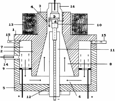
Brief Description of the drawing, which shows a general view of the device. Device for obtaining thermal energy of hydrogen and oxygen comprises a housing 1 made of dielectric material which has a lower 2 and upper 3 flushes with an axial hole 4 and lower cover 5, transconductance chamber 6, divided by a lower cylindrical tide 2 on anode 7 and cathode 8 cavity, the anode 9 is a flat ring with openings and is situated in the anode cavity transconductance chamber and a rod cathode 10 made of refractory material, is located in the dielectric rod 11 with an external thread by which it is introduced into the interelectrode chamber through a threaded hole 12 in the bottom cover and is centered in the outlet hole, forming together with the upper cylindrical tide housing near the cathode cavity, the permanent magnet 13 of cylindrical shape is put on the upper cylindrical tide 3 and its magnetic field covers the cathode and near the cathode cavity, the pipe 14 entering the working solution is in the middle anode cavity portion, and pipes 15 for the withdrawal of oxygen installed at the top of the anode cavities, and output port 16 for the gas mixture is located in the upper cylindrical tide. |
DEVICE FOR HEAT, hydrogen and oxygen
WORKS AS FOLLOWS
The anode 7 and cathode 8 of the cavity is filled with a weak solution of acid or alkali through pipe 14 and set the required flow rate of the solution. The device is then connected to the power supply and a DC voltage was gradually increased until a stable plasma. The cathodic chamber 8 occurs solution heated to reflux with partial decomposition of water into hydrogen and oxygen. Oxygen evolved at the anode, rises to the top of the anode chamber 7 through pipes 15 and is removed from the anode cavity.
Molecular hydrogen gas, which is formed at the plasma-fluid collected in the upper part of the cathode cavity and out along with water vapor through the outlet.
Under the influence of an electric field between the cathode repeatedly reduced area 10 relative to area of the anode 9 to the cathode forms a focused stream of alkali metal ions. Having kinetic energy reserve when moving towards the cathode, alkali metal ions are separated from the protons of water molecules hydrogen atoms and hydrogen atoms. As a result, the cavity is formed in the cathode plasma atomic hydrogen. The energy source is the processes of synthesis of hydrogen atoms and molecules.
The presence in the plasma zone of an electric field except for a constant magnetic field intensifies the water heating process and its decomposition into hydrogen and oxygen. This increases the energy efficiency of the process.
Thus, at the cathode hydrogen plasma heat source is transmitted aqueous solution, and a source of atomic and molecular hydrogen and oxygen simultaneously.
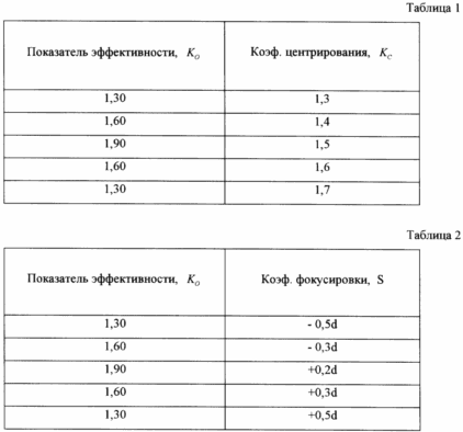
The effectiveness of the process depends on many factors. The main factors of the coefficient K are centered with the cathode 10 and the focusing coefficient S. centering size ratio defined by the formula
With K = D / d, (1)
where D - diameter of the through hole 3;
d - diameter of the cathode 10.
It was established experimentally that the optimum value of the coefficient K C centering the cathode 10 is in the range 1,3 <K <1.7 and the focusing coefficient S, which determines the magnitude of the cathode 10 into a cylindrical entrance portion of the nozzle through hole 16 varies (-0,5d <S <+ 0,5d). The minus sign means that the cathode 10 does not reach the outlet opening by the amount 0.5d, and the plus sign - the cathode inlet 10 into the hole on the value of 0.5d.
Efficiency of the device determines the total efficiency rate of K, taking into account the electrical energy E e, introduced into the device, the thermal energy E t, which is accumulated in the heated aqueous solution and steam, and the energy E g, contained in the separated gases: hydrogen and oxygen.

It is experimentally established that, taking into account only the energy contained in the heated aqueous solution and water vapor performance indicator takes the value of K = 1,7 ± 0,20. Approximate records released gases increases this figure to 1,9 ± 0,20 (Table. 1, 2).

CLAIM
Device for obtaining thermal energy of hydrogen and oxygen, comprising a housing with an axial hole, nozzle input working solution transconductance cell anode connected to the positive power source and a cathode connected to a negative power supply pole, a permanent magnet, characterized in that the housing, made of dielectric material has upper and lower inflow and lower cover forming the transconductance chamber divided lower cylindrical tide on the anode and cathode chamber, wherein the anode is a flat ring with openings located in the anode chamber transconductance chamber and rod cathode made of refractory material, is located in a dielectric rod with an external thread by which it is introduced into the interelectrode chamber through a threaded hole in the bottom cover and is centered in the outlet hole, forming together with the upper cylindrical tide housing near the cathode cavity, a permanent magnet of cylindrical shape is put on the upper cylindrical tide and its magnetic field near the cathode and covers the cathode chamber, wherein the working solution inlet I located in the middle part of the anode chamber and output connections for oxygen are set at the top of the anode chamber, wherein the output tube for gas mixture located in the upper cylindrical tide.
print version
Publication date 02.03.2007gg


Comments
Commenting, keep in mind that the content and the tone of your messages can hurt the feelings of real people, show respect and tolerance to his interlocutors, even if you do not share their opinion, your behavior in terms of freedom of speech and anonymity offered by the Internet, is changing not only virtual, but real world. All comments are hidden from the index, spam control.