
| Start of section
Production, amateur Radio amateurs Aircraft model, rocket-model Useful, entertaining |
Stealth Master
Electronics Physics Technologies Inventions |
Secrets of the cosmos
Secrets of the Earth Secrets of the Ocean Tricks Map of section |
  |
| Use of the site materials is allowed subject to the link (for websites - hyperlinks) | |||
Navigation: => |
Home / Patent catalog / Catalog section / Back / |
|
INVENTION
Patent of the Russian Federation RU2105235
![]()
VESSEL FOR STORAGE OF CRYOGENIC LIQUID
The name of the inventor: Fedotov V.K.
The name of the patent holder: SP Korolev Rocket and Space Corporation Energia
Address for correspondence:
Date of commencement of the patent: 1996.12.06
Use: The invention relates to the field of cryogenic technology and is intended for storing cryogenic liquids in a vessel with open drainage under conditions of reduced gravity. SUMMARY OF THE INVENTION: The cryogenic liquid storage vessel comprises a thermally insulated inner shell fixed to supports in a vacuum-tight outer shell and refueling and drainage piping. In the cavity of the inner shell of the vessel at the intake end of the drainage pipeline there is installed a perforated tip made of a material that is not wetted by cryogenic liquid and located in the area of attachment of one of the supports, the total perforation area of said tip not less than the area of the drainage pipeline, Cavity of the inner shell and on its section between the inner and outer shells are installed cylindrical spacers made of non-wettable cryogenic liquid material whose diameter exceeds the diameter of said drainage pipeline. The proposed technical solution, in comparison with the known technical solutions, allows to exclude losses of cryogenic liquid due to its leakage from the vessel under the influence of surface tension forces when storing cryogenic liquid in a vessel with open drainage under conditions of reduced gravity.
DESCRIPTION OF THE INVENTION
The invention relates to the field of cryogenic technology and is intended for storage of cryogenic liquids under conditions of reduced gravity.
Known for the analogue, a vessel for storing a cryogenic liquid (see the Handbook on the Physical and Technical Basics of Cryogenics.) Edited by MP Mal'kova, Moscow: Energia, 1973, p. 339). The vessel contains a thermally insulated inner sheath fixed in a vacuum-tight outer shell at the neck, through which the cryogenic liquid is refilled and drained during storage.
There is also a known vessel for storing a cryogenic liquid, chosen as a prototype (see Kaganer, MG, Thermal Isolation in Low Temperature Engineering, M.: Mechanical Engineering, 1966, p.260, pic.117). The vessel contains a thermally insulated inner shell fixed to the supports in a vacuum-tight outer shell and a drainage-refueling pipeline.
The disadvantage of the analog and prototype is that they do not exclude the loss of cryogenic liquid due to it from the vessel under the influence of surface tension forces when storing cryogenic liquid in a vessel with open drainage under conditions of reduced gravity. As a result, the storage time of the cryogenic liquid in the vessel, which in terrestrial conditions depends only on heat inflows to the stored liquid from the environment through the thermal insulation and thermal bridges, will be substantially reduced.
It is an object of the present invention to provide a cryogenic liquid storage vessel whose design allows the loss of cryogenic liquid to be eliminated by flowing out of the vessel under the action of surface tension forces while storing the cryogenic liquid in an open drainage vessel under reduced gravity conditions.
The essence of the invention lies in the fact that a perforated tip made of non-wettable cryogenic liquid is installed in the cavity of the inner shell at the intake end of the drainage pipeline in a cryogenic liquid storage vessel containing a heat-insulated inner shell fixed on the supports in a vacuum-tight outer shell and filling and drainage lines. Material and located in the area of attachment of one of the supports, the total perforation area of said tip being not less than the area of the drainage pipeline cross-section, and at the outlet of the drainage pipeline from the cavity of the inner shell and in its section between the inner and outer shells, spacers made of non-wettable Cryogenic liquid of a material whose diameter exceeds the diameter of said drainage conduit.
The technical result is that, in comparison with the currently known technical solutions, the newly created design eliminates the leakage of cryogenic liquid from the vessel under the influence of surface tension forces when storing cryogenic liquid in an open drainage vessel under conditions of reduced gravity.
This is achieved in that, firstly, in the proposed design, a perforated tip is installed in the cavity of the inner shell at the intake end of the drainage pipeline, made of a material that is not wetted by cryogenic liquid, which is located in the zone of the greatest local heat transfer to the cryogenic liquid - in the zone of attachment to the inner shell Thermal bridge, t. In this zone, with a chaotic arrangement of the liquid and vapor phases under zero-gravity conditions, the vapor phase is most likely to be. If a liquid phase enters this zone, then when it comes into contact with a perforated tip from a material that is not damped with cryogenic liquid, it will not spread over its surface, but will only touch it at separate points and steam will be drawn into the perforated apertures of the tip. Secondly, for a greater guarantee of excluding leakage of the cryogenic liquid under the action of surface tension forces, at the point of exit of the drainage pipeline from the cavity of the inner shell and in its section between the inner and outer shells, cylindrical spacers are constructed, made of a material that is not wet with a cryogenic liquid, whose diameter exceeds the diameter Drainage pipeline on which they are installed. This is done so that if some fraction of the liquid passes through the perforated tip, then the surface tension force, by which the fluid moves along the pipeline wall, will be reduced by as much as the diameter of the spacer is greater than the diameter of the pipeline and, In addition, the liquid can not move along the surface of the attachment, since it is made of a material that is not wetted by the cryogenic liquid.
The essence of the invention is explained by the drawing.
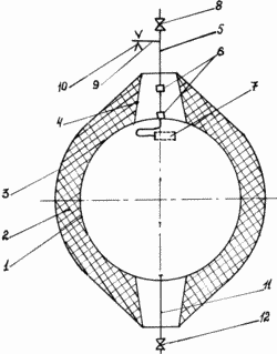 |
The vessel for storing the cryogenic liquid consists of the following main units and parts: the inner shell 1, covered with thermal insulation 2 and fixed in the outer shell 3 by means of supports 4; Drainage line 5 at the outlet of which from the inner shell 1 and in its section between the inner and outer shells spacers 6 made of non-wettable cryogenic liquid material, for example of GRP, are installed, and on the intake end of the drainage pipeline 5 which is located in the inner shell 1 , A perforated ferrule 7 is provided, made of non-wettable cryogenic liquid material, for example, fiberglass; On the drainage line 5, after exiting it from the outer shell 1, a check valve 8 is installed and before the shut-off valve 8, a conduit 9 with a restrictive washer 10 is docked to the drainage line 5; In the vessel is a filling line 11 with a shut-off valve 12. |
DEVICE WORKS AS FOLLOWING
On Earth, the vessel is charged with a cryogenic liquid through the pipeline 11. The vapor drainage is carried out through the pipeline when refueling. The shut-off valves 8, 12 are open during filling. After the completion of the filling, the valves 12, 8 are closed in series and the vapor is drained afterwards only through the pipeline 9 with the restrictive washer 10. After the vessel is discharged into space, the vapor drainage is carried out via line 9 with a restrictive washer 10, which is designed to maintain pressure In the vessel at the accepted level, with the drainage of vapors into outer space. When the vessel is operating under conditions of reduced gravity, the arrangement of the liquid and vapor phases in the vessel is arbitrary. If the material of the inner shell is wetted by a cryogenic liquid, a part of the liquid phase will be located along the surface of the inner shell. Usually the shells of vessels are made of metal, and metals are wetted by all cryogenic liquids. However, in the zone of attachment of the support there is a local supply of heat. The heat flux density is greater there than in the rest of the shell, so the shell temperature will be higher here. The coefficient of surface tension of cryogenic liquids decreases with increasing temperature, therefore in this zone the probability of the liquid lying on the wall of the shell is small. If there is liquid in the area of the tip 7, due to the fact that the tip material is not wetted by the cryogenic liquid, it will not spread over the surface of the tip, but will touch it at separate points and a vapor phase will be taken into the orifices of the tip, the flow rate of which is determined Only by heat inflows to the stored cryogenic liquid through thermal insulation and thermal bridges and which is known in advance. In case of penetration of some fraction of the liquid phase into the orifices of the tip, its movement along the walls of the drainage pipeline 5 to the restrictive washer 10 is excluded, since Spacers from a non-wettable cryogenic liquid material with a diameter exceeding the diameter of the pipeline are installed on the drainage pipeline 5, which leads to a decrease in the surface tension force. With further movement, a small fraction of the liquid that has entered the drainage line evaporates until it reaches the restrictive washer. In known devices, when a liquid phase hits the intake end of a drainage pipeline, it will move due to surface tension forces, whose role under zero gravity is significant, since gravitational forces that counteract them on the Earth are absent and the liquid will be discharged through the drainage pipeline to the environment. The liquid release mode will continue until the liquid phase is at the intake opening of the drainage pipeline, while the flow of liquid from the vessel is determined not by heat influxes but by the action of surface tension forces.
Thus, in comparison with the known technical solutions, the proposed device allows to exclude losses of cryogenic liquid due to its leakage from the vessel under the influence of surface tension forces when storing cryogenic liquid in a vessel with open drainage under conditions of reduced gravity.
CLAIM
A vessel for storing a cryogenic liquid containing a thermally insulated inner shell fixed to the supports in a vacuum-dense outer shell and filling and drainage pipelines characterized in that a perforated tip made of a non-wettable cryogenic liquid material is installed in the cavity of the inner shell at the intake end of the drainage pipeline And located in the area of attachment of one of the supports, the total perforation area of said tip being not less than the area of the drainage pipeline cross-section, and at the outlet of the drainage pipeline from the cavity of the inner shell and in its section between the inner and outer shells, cylindrical spacers made of non-wettable Cryogenic liquid of a material whose diameter exceeds the diameter of said drainage conduit.
print version
Date of publication 28.02.2007gg
![]()

Comments
Commenting on, remember that the content and tone of your message can hurt the feelings of real people, show respect and tolerance to your interlocutors even if you do not share their opinion, your behavior in the conditions of freedom of expression and anonymity provided by the Internet, changes Not only virtual, but also the real world. All comments are hidden from the index, spam is controlled.