| Start of section
Production, amateur Radio amateurs Aircraft model, rocket-model Useful, entertaining |
Stealth Master
Electronics Physics Technologies Inventions |
Secrets of the cosmos
Secrets of the Earth Secrets of the Ocean Tricks Map of section |
|
| Use of the site materials is allowed subject to the link (for websites - hyperlinks) | |||
Navigation: => |
Home / Patent catalog / Catalog section / Back / |
|
INVENTION
Patent of the Russian Federation RU2270788
![]()
TANK FOR CRYOGENIC FUELS
The name of the inventor: Semenov Vyacheslav Lvovich (RU); Kleankin Heinrich Alekseevich (RU); Dudareva Nina Nikolaevna (RU); Shchekareva Irina Gennadievna
The name of the patent holder: Federal State Unitary Enterprise "Central Institute of Aviation Motors named after PI Baranov"
Address for correspondence: 111116, Moscow, ul. Aviamotornaya, 2, FSUE "CIAM named after PI Baranova", Department of Intellectual Property
Date of the beginning of the patent: 2004.08.23
The invention relates to fuel systems of transport vehicles, in particular aerospace vehicles, namely to on-board vessels for storage and supply of cryogenic fuel, for example hydrogen. The offered capacity contains a sealed protective casing, an internal vessel with thermal insulation, pipelines for refueling, drainage - pressurization and fuel supply, and a fence. The inner vessel is attached to the protective casing on two supports containing thin-walled bodies of rotation, for example, a conical shape with heat-shielding ring spacers and screen-vacuum heat insulation. One of the thin-walled bodies of rotation is connected to a sleeve telescopically connected to a cylinder attached to the inner vessel. This ensures the relative movement of the inner vessel and protective casing. In a preferred embodiment, the sampling device comprises rigidly connected check valves communicating with the fuel sampling conduits with cavities near the respective bottoms of the inner vessel. These valves are controlled by an electro-pneumatic system. The technical result of the invention is to provide long-term non-drainage storage of cryogenic fuel during parking of the vehicle, as well as continuous fuel sampling under alternating acceleration during the movement.
DESCRIPTION OF THE INVENTION
The proposal relates to a fuel supply system for vehicles, namely to onboard tanks for storage and supply of cryogenic fuel, for example hydrogen when used as an energy carrier in vehicles.
A serious obstacle in the development of on-board tanks for liquid hydrogen is the low boiling point (21 K), high fluidity, fire and explosion hazard. The onboard tanks for liquid hydrogen of the carrier rockets Saturn-5 USA, Energia Russia, Ariane-5 Europe [1, 2, 3], in whose rocket engines liquid hydrogen is used as a fuel component of fuel are known. These tanks are cylindrical vessels with elliptical bottoms. They had sufficiently large diameters and lengths and were made of metal with thermal insulation made of a durable synthetic material applied to the outer surface of the vessel.
A disadvantage of these air tanks is that, due to large heat influxes, no hydrogen storage of hydrogen is ensured therein. The hydrogen is fed into these tanks before the rocket starts. At this point, the drain valve closes and the hydrogen supply valve from the on-board vessel opens into the rocket engines, which operate during the entire flight before the stage is separated. The intake of hydrogen in such tanks is made only from the bottom bottom, since the acceleration of the rocket in the removal of the space object is always positive. Therefore, tanks of this type can not be used, for example, in airplanes or cars where braking or long-term parking is possible, for which non-hydrogen storage of hydrogen is required.
The closest technical solution chosen for the prototype is a cryogenic fuel tank according to US Pat. No. 6,643,519, which contains a sealed protective casing, an inner vessel with thermal insulation, refueling lines, drainage-pressurization and fuel supply, and a sampling device. The inner vessel has a cylindrical shape with elliptical bottoms. The walls of the inner vessel do not have a rigid connection with the walls of the protective casing. The walls of the inner vessel and the protective cover are aligned along the layer of thermal insulation. Such a design of the onboard tank has a significant drawback associated with increased heat influx to the walls of the inner vessel through the multi-layer thermal insulation, and as a consequence, the time of the non-drainage storage of cryogenic fuel in this container is slightly.
In addition, the absence of a rigid connection between the inner vessel and the outer casing does not allow the vehicle to operate in large alternating accelerations and vibrations during movement. Thermal deformations of the inner vessel will lead to flaking of the thermal insulation after a few refills and emptying of the inner vessel.
The proposed container differs from the prototype in that the inner vessel is attached to the protective casing on two supports containing thin-walled bodies of revolution, for example of a conical shape with heat-shielding annular spacers and screen-vacuum thermal insulation, in one of the supports a thin-walled body of rotation fixed to the casing, Is connected to a sleeve telescopically connected to a cylinder attached to the inner vessel, which provides a relative movement of the inner vessel and the protective cover.
The proposed container is characterized in that the intake device comprises rigidly connected check valves communicating with cavities near each bottom of the inner vessel and controlled by an electro-pneumatic system.
The objective of this proposal is to create a container for cryogenic fuel with a long period of its non-drainage storage on board the vehicle and with the constant collection of cryogenic fuel from the tank, regardless of its flow along the inner vessel under alternating accelerations while the vehicle is moving.
The technical result, which allows to significantly reduce the heat inflow to the cryogenic fuel and increase the time of the non-drainage storage, is achieved by the fact that the cryogenic fuel tank contains a sealed protective casing, an inner vessel with thermal insulation, fueling, drain-inflation and fuel supply lines, and a fence This inner vessel is attached to the protective casing on two supports containing thin-walled bodies of rotation, for example of a conical shape with heat-shielding annular spacers and screen-vacuum thermal insulation, in one of the supports a thin-walled body of rotation fixed to the casing is connected to a sleeve telescopically connected to A cylinder attached to the inner vessel, which provides a relative movement of the inner vessel and the protective casing. The technical result is achieved by the fact that the intake device comprises rigidly connected check valves communicating with cavities near each bottom of the inner vessel and controlled by an electro-pneumatic system.

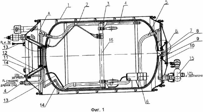
FIG. 1 shows a longitudinal section of an on-board vessel for storing and supplying cryogenic fuel.

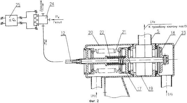
FIG. 2 shows a longitudinal section of a two-position sampling device with elements
Onboard control system.
 |
 |
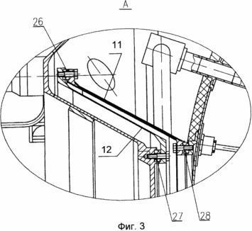
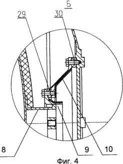
3 shows the left fixed support of the inner vessel. 4 shows the right
Movable support of the inner vessel.
The onboard container consists of a protective casing 1, an inner vessel 2 with screen-vacuum heat insulation 3, a drain-boost pipeline 4, a fuel supply pipe 5 from a two-position intake device 6, a movable support 7 in the form of a cylinder 8 telescopically entering a cylindrical bush 9 fixed At the end of a thin-walled body of rotation 10, a stationary support 11 with a thin-walled body of revolution 12. A pipe fitting 13 is installed on the protective cover 1 to supply the helium command pressure to the two-position intake device 6, the nozzle 14 of the cryogenic fuel filling line and the starting valve 15. In the inner vessel And a level gauge 16 for monitoring the fuel level during refueling.
The two-position sampling device 6 (FIG. 2) has two shut-off valves: a cryogenic fuel sampling valve 17 from the left bottom and a valve 18 for taking the cryogenic fuel from the right bottom. Both valves are rigidly connected to each other through the cylindrical shank of the valve 17 and are centered in the guides of the housing 19, which is provided with sealing seats made of polycarbonate. The valve 17 is located inside the casing 20 and is hermetically connected to it through a bellows 21 whose internal cavity is connected to the helium command pressure delivery terminal 13. In the initial position, the valve 17 is pressed against the seat seat 19 by the spring 22. The valve 18 is housed in a casing 23 provided with a sampling tube lowered downwards. When the boost pressure is applied to the inner vessel 2 (FIG. 1), through the conduit 4, the valve 17 is opened and the valve 18 is closed. After that, the change of the places of the intake of the fuel is effected by the supply or discharge of the helium pressure into the bellows cavity from the airborne electropneumatic valve 24 from the signals of the on-board accelerometer 25. One of the stop valves (17 or 18) opens and the other closes.
Thin-walled rotation bodies 10, 12 are provided with heat-insulating ring spacers 26, 27, 28, 29, 30 and screen-vacuum heat insulation (FIG. 3 and FIG. 4).
The process of operating a tank on board a vehicle consists of four operations:
- Technological preparation of the tank for filling operations.
- Refueling of cryogenic fuel.
- Storage of cryogenic fuel in an inner vessel.
- Delivery of cryogenic fuel to the consumer.
During the refueling of the cryogenic fuel, the tanker's pipeline is connected to the fitting 14 of the filling line and the cryogenic fuel is fed to the lower part of the inner vessel 2. At the same time, the side drainage valve (not shown) is opened on the pipeline 4. The filling of the inner vessel is monitored by level 16 and by signals of thermoelectric Sensors (not shown) mounted on the wall surface of the inner vessel 2.
At the end of the refueling, the on-board filling and drain valves are closed and the cryogenic fuel is inside the tank until it is used in the engine.
When the engine is turned on, the start-up valve 15 and the boost valve of the tank (not shown) are opened. In this case, the preset pressure is set in the vessel, and the cryogenic fuel through the valve 15 is supplied to the consumer.
In the process of filling the tank with cryogenic fuel, the wall temperature changes by at least 250 °, which leads to thermal narrowing in the longitudinal and diametral directions. In the longitudinal direction, the variation in the length of the vessel is compensated by the displacement of the cylinder 8 in the sleeve 9. In the diametrical direction, the size of the inner vessel varies freely, since the screen-vacuum heat insulation is elastic, and the inner vessel does not touch the casing in this direction.
Screen-vacuum heat insulation of the wall and bottoms of the inner vessel, deep vacuum inside the protective casing and heat-separating devices in the supports minimize the heat inflow to the walls of the inner vessel, which ensures long-term storage of cryogenic fuel, for example, during parking of the vehicle or when driving with the engine off .
A two-position intake device 6, controlled by an electro-pneumatic system with a valve 24, which is connected to the accelerator accelerometer 25, provides for the supply of cryogenic fuel to the engine under alternating accelerations causing fuel flow inside the vessel.
Several copies of this design were manufactured and showed good results in testing.
USED BOOKS
1. JASehlke "ZRE Rokitdyne J-2", Astronauties, 1962, vol. 7, No. 2, p. 41, 98.
2. ABBeiley, RGGruddace, WARicketson "The application of the liquid hydrogen for rokot therd stage of satellite". Journal of the British Interplanetary Society, 1961, vol. 18, No. 5-6, h.203-224.
3. Ariane 5, Cryospase, Aerospatiale, France. 2001.
CLAIM
1. A container for cryogenic fuels, comprising a sealed protective casing, an inner vessel with thermal insulation, fueling, drain-inflation and fuel supply pipes, and a sampling device characterized in that the inner vessel is attached to the protective casing on two supports containing thin-walled bodies of revolution , For example, conical shaped, provided with heat-shielding ring spacers and screen-vacuum heat insulation, and in one of the supports said thin-walled body of rotation fixed to the housing is connected to a sleeve telescopically connected to a cylinder attached to the inner vessel, providing relative displacement of the inner vessel and Protective cover.
2. A container as claimed in claim 1, characterized in that the intake device comprises rigidly connected check valves communicating with their respective cavities near the bottoms of the inner vessel and controlled by the electro-pneumatic system.
print version
Date of publication 28.02.2007gg


Comments
Commenting on, remember that the content and tone of your message can hurt the feelings of real people, show respect and tolerance to your interlocutors even if you do not share their opinion, your behavior in the conditions of freedom of expression and anonymity provided by the Internet, changes Not only virtual, but also the real world. All comments are hidden from the index, spam is controlled.