
| section Home
Production, Amateur Radio amateur Model aircraft, rocket- Useful, entertaining |
Stealth master
Electronics Physics Technologies invention |
space Mystery
Earth Mysteries Secrets of the Ocean Stealth section Map |
  |
| Use of material is permitted for reference (for websites - hyperlinks) | |||
Navigation: => |
Home / Products Patents / In the section of the catalog / back / |
|
INVENTION
Russian Federation Patent RU2226047
![]()
REACTOR FOR ANAEROBIC FERMENTATION LIQUID ORGANIC WASTE
Name of the inventor: Puzankov AG .; Mkhitaryan GA
The name of the patentee: Puzankov Anatoly; Mkhitaryan Grant Aleksanovich
Address for correspondence: 129348, Moscow, Yaroslavl sh, 8, building 2, kv.356, A.G.Puzankovu.
Starting date of the patent: 2003.01.21
The invention relates to agriculture, and is intended for processing of liquid manure or manure into organic fertilizer and combustible biogas. The reactor comprises a vertical insulated fermentation tank with a conical bottom and formed in the shape of a dome roof, the central part of which is mounted gas gathering hood, a vertical central tube coaxially mounted within the fermentation tank at the gas gathering hood communicating with the latter and do not reach the bottom of the fermentation tank, the device for gas pressure equalization in the central tube and cupola zone fermentation tank connected from the top to the gas collecting hood gas pipeline connected to the gas pump and gazonakopitelnoy capacity, a device for heating the fermentation vessel and reported to her pressure loading line, unloading pipe and overflow pipe, a control unit, the shut-off valve with actuator and valve pneumohydraulic. In the center of the conical bottom of the fermentation tank holds an outlet that is connected to the unloading pipe with a shut-off valve built-in. Pneumohydraulic valve consists of a hollow float open bottom and mounted within the central tube in a vertically reciprocating along its movement limited in the top position of the float stops attached to the inner surface of the central tube, rigid axial longitudinal member fixed within a hollow float shut-off valve attached from below to said element to overlap the outlet opening in the bottom of the fermentation tank in the lowest position of the float, an additional pipeline connected on top to a hollow float and having a switch for its alternately connecting the suction nozzle of the gas pump or the gazonakopitelnuyu container with discharge port of the gas pump. Device for equalizing the gas pressure in the central zone of the tube and cupola fermentation vessel is designed as a siphon through which the ascending branch of the hydraulic valve in communication with the fermentation tank and the descending branch - is introduced from the top into the central pipe. Gas gathering cap recessed in the fermentation tank so that its lower edge is located below the inlet of the ascending branch of the siphon. Switch additional pipeline and drive stopcock unloading pipe connected to the control unit. The invention provides a more efficient removal of sediment from the fermentation tank through an intensification of mixing fermented mass in the zone of deposition and prevent compaction of sediment due to the controlled turbulence precipitate at the time of the removal of specified intervals.
DESCRIPTION OF THE INVENTION
The invention relates to agriculture, and is intended for the treatment of liquid organic waste, mainly manure or litter, and produce environmentally friendly organic fertilizer and combustible biogas.
Known reactor for the anaerobic digestion of liquid organic waste, such as manure, containing insulated fermentation tank with a water jacket, connections for input and output of the fermentation mass, vertical, central tube coaxially mounted within the fermentation tank, not reaching to the last bottom, made with double walls, having guide elements on the outer surface and the top of the sleeve for escape of biogas, wherein the central tube is provided with a gravity line which is formed as a sloping pipe with an adjustable valve communicated upper end to the upper part of the inner cavity of the central tube, and the lower end - with fermentation capacity, the lower end of the sleeve is immersed in the fermentation mass, and the guide elements are designed as movable blades mounted mutually inclined to each other (see. USSR author's certificate №1152541, IPC a 01 C 3/00, published 04.30.1985).
Disadvantages of this known reactor are the low efficiency of removal of the solid precipitate fraction especially during the fermentation of semi-liquid manure or highly concentrated waste due to rapid compression of sludge in the area of the lower end of the central tube, long duration of the fermentation process due to non-intensive mixing of the fermentation mass of the movable blade having no drive high korkoobrazovanii fermentation mass on the surface at the top of the fermentation tank.
The closest to the proposed reactor analogue of the technical essence is known reactor for anaerobic digestion of organic liquid waste, mainly manure and litter containing vertical insulated fermentation tank with a conical bottom and formed in the shape of a dome roof, the central part of which is mounted gas gathering hood, a vertical central tube coaxially mounted within the fermentation tank under gas gathering cap, communicating with the latter and extends to the bottom of the fermentation tank, the device for aligning the gas pressure in the central tube and cupola zone fermentation tank connected from above to the gas collecting hood pipeline connected to the gas pump and gazonakopitelnoy capacity, a device for heating the fermentation vessel and reported to her pressure loading line, unloading piping and the overflow pipe (see. patent the Russian Federation №2162626, IPC a 01 C 3/00, published 10.02.2001).
In this known reactor gas pump climbs biogas fed into the fermentation tank bottom to form a fine dispersed popup biogas stream that mixes the fermentation mass and provides constantly "boiling" surface fermented in a fermentation vessel mass, preventing the formation of a dense cake on this surface.
A disadvantage of the known reactor lies in the ineffective removal of the solid precipitate fraction due to low intensity mixing in the fermentation mass precipitation zone due to the fact that release biogas flow is upstream of the zone.
The object of the invention is to expand the arsenal of hardware designed for the anaerobic digestion of organic liquid wastes, with an increase in the efficiency of removal of sediment from the fermentation tank through an intensification of mixing fermented mass in the deposition zone and to prevent the sediment compaction due to the controlled turbulence of the precipitate at the time of the removal of specified intervals .
The solution of this problem is achieved by the fact that the reactor for the anaerobic digestion of organic liquid waste, mainly manure and litter containing vertical insulated fermentation tank with a conical bottom and formed in the shape of a dome roof, the central part of which is mounted gas gathering hood, a vertical central tube coaxially mounted within fermentation tank under gas gathering hood communicating with the latter and do not reach the bottom of the fermentation tank, the device for aligning the gas pressure in the central tube and cupola zone fermentation tank connected from the top to the gas collecting hood gas pipeline connected to the gas pump and gazonakopitelnoy capacity, a device for heating the fermentation capacity and reported her pressure loading line, unloading pipe and overflow pipe according to the invention is provided with a control unit, shut-off valve with a drive and pneumohydraulic valve, and in the center of the conical bottom of the fermentation tank holds an outlet that is connected to the unloading pipe with built in it mentioned stopcock and pneumohydraulic valve consists of a hollow float open bottom and mounted within the central tube in a vertically reciprocating along its movement limited in the top position of the float stops attached to the inner surface of the central tube, rigid axial longitudinal member fixed within the hollow float shut-off valve attached from below to said element to overlap the outlet opening in the bottom of the fermentation tank in the lowest position of the float, an additional pipeline connected on top to a hollow float and having a switch for its alternately connecting the suction nozzle of the gas pump or the gazonakopitelnuyu container with discharge fitting the gas pump, the apparatus for equalizing the gas pressure in the central tube and cupola area of the fermentation vessel is designed as a siphon rising branch which via the hydraulic valve in communication with the fermentation tank and the descending branch is introduced from above into the central tube, wherein the gas gathering cap recessed in fermentation tank so that its lower edge is located below the inlet of the ascending branch of the siphon, moreover, an additional pipeline and switch actuator stopcock unloading conduit connected to the control unit.
In the particular cases of structural embodiment of a reactor for anaerobic digestion of organic liquid wastes:
- Loading line pressure introduced into the central tube, and its end is located below the inlet of the ascending branch of the siphon;
- Drive pressure pump loading line coupled to the control unit;
- Introduced into the central pipe from above the descending branch of the siphon is adjustable of its length;
- Overflow pipe is connected through a hydraulic valve with a constant pipeline unloading;
- A device for heating the fermentation vessel is in the form of its bottom water jacket, communicating with the heating unit.
Brief Description of the drawing, which shows a reactor for anaerobic fermentation of organic waste liquid, a schematic diagram of a vertical sectional view of a fermentation tank at its axis.
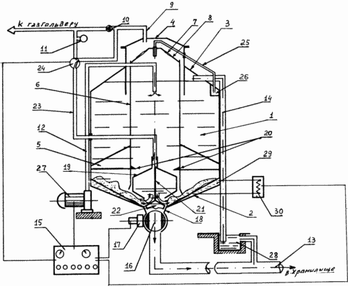
Reactor for anaerobic fermentation of organic waste liquid comprises a vertical fermentation tank 1 insulated from the conical bottom 2 and formed as a dome roof 3. The central portion 3 of the roof mounted gas gathering cap 4 and the cap under the gas gathering inside the fermentation vessel 4 using 1 attached to its inner the surface of the bracket 5 is coaxially mounted a vertical central pipe 6, not reaching to the bottom of the fermentation tank 1. 2 vertical central pipe 6 through holes 7 formed in its upper domed ceiling 8, communicates with the gas gathering 4. top cap to the gas collection hood 4 is connected the pipeline 9, associated with the gas pump 10 and gazonakopitelnoy capacity of 11. in this case, the reactor for the anaerobic digestion of organic waste liquid has a device to equalize gas pressure in the central tube 6 and cupola zone fermentation tank 1, a device for heating the fermentation tank 1 and reported to her pressure loading line 12 , unloading duct 13 and overflow pipe 14. The discharge pipe 12 insulated boot, for example laid by insulating coating it is advisable to carry out the fermentation tank 1.
In addition, the reactor for the anaerobic digestion of organic waste liquid is provided with a control unit 15, a stopcock 16, for example a ball or slug with pneumohydraulic actuator 17 and valve. In the center of the conical bottom 2 of the fermentation tank 1 holds the outlet 18 to which is connected the unloading conduit 13 with built-in shut-off valve 16. It Pneumohydraulic valve consists of a hollow float 19, and an open bottom mounted inside the central pipe 6 in a vertically reciprocating along its movement limited in the top position of the float 19 stops 20 attached to the inner surface of the center tube 6, the hard axial longitudinal element 21 fixed within a hollow float 19, check valve 22 attached from below to the hard axial longitudinal element 21 to overlap the outlet opening 18 in the bottom 2 of the fermentation tank 1 in the lower position of the float 19, an additional pipeline 23 telescopically or by a siphon, connected on top to a hollow float 19 and having a switch 24 to its alternate connection to the suction port of the gas pump 10, or through gazonakopitelnuyu vessel 11 with discharge pipe the gas pump 10.
Device for equalizing pressure in the central gas pipe 6 and cupola zone fermentation tank 1 designed as a siphon 25, which is the ascending branch through the hydraulic valve 26 communicates with the fermentation tank 1, while the descending branch is introduced from above into the central tube 6. The gas-collection hood 4 is recessed into the fermentation container 1 so that its lower edge is located below the inlet of the ascending branch of the siphon 25. The switch 24 further pipeline 23 and the actuator 17 stopcock 16 of the unloading conduit 13 connected to the control unit 15 to work them mutually.
Pressure loading line 12 connected to the feed pump 27 is entered into the central pipe 6 and its end is located below the inlet of the ascending branch of the siphon 25, i.e. recessed below the lower level of the fermentation mass. Drive 27 Pump pressure loading line 12 is connected with the control unit 15.
Introduced from above into the central pipe 6 descending branch 25 of the siphon is adjustable of its length, for example made telescopic.
Overflow pipe 14 is connected through a constant hydraulic valve 28 with unloading pipe 13.
Device for heating the fermentation tank 1 is made as a water jacket 29 2 of its bottom, communicating with the heating unit 30, which is connected to control unit 15.
Reactor for anaerobic fermented liquid organic waste operates as follows.
Liquid organic wastes, especially liquid manure or dung, humidity not less than 85%, is fed by a pump 27 through the pressure loading line 12 into the fermentation tank 1, filling it to the top-level storage tank of the hydraulic valve 26, wherein the fermented liquid mass closes a hydraulic gate 26, an inlet of the ascending branch of the siphon 25 and the lower edge of the gas collection hood 4 is immersed in the fermentation tank 1 at the level of the fermentation mass.
In the case of exceeding the filling level of the fermentation tank 1, an excess amount of fermented liquid mass is discharged by an overflow pipe 14 in the unloading line 13 through constant hydraulic valve 28, which prevents the flow of air into the fermentation tank 1.
Thereafter, the control unit 15 includes a heating unit 30, performing heating of the bottom of the water jacket 29 2 of the fermentation tank 1 and the fermentation liquid in the final mass to a predetermined temperature, and then the pump 10 includes a gas.
Gas pump 10, taking away the gas from the gas collection cap 4 creates therein a vacuum under the influence of which the central tube 6 communicating with the gas cap 4 via holes 7 formed in its upper domed ceiling 8 fermenting mass rises, and in the fermentation tanks 1 - goes down. At the same time through the siphon 25 of fermentable mass storage tank hydraulic valve 26 flows into the central tube 6. As a result of emptying the storage tank of the hydraulic valve 26 opens the inlet of the ascending branch of the siphon 25 and the latter connects the gas-filled cavity in the cupola area of the fermentation tank 1 and the top of the vertical central tube 6 at its upper domed ceiling 8, whereby the gas pressure in said cavity aligned and post fermentation mass of the central tube 6 raised earlier by the gas pressure difference in said cavities, under gravity falls down the center tube 6 and, passing through the annular gap between the inner surface of the central tube and the outer surface 6 of the hollow float 19, forming an annular flow, and disintegrating the cake slurried conical bottom 2 of the fermentation tank 1, i.e. mixing the fermented mass into the deposition zone. In the gas-collection hood 4, the cavity of which communicates with the cavity of a vertical central pipe 4 through the holes 7 in the upper domed ceiling 8 of the latter, and the gas pressure becomes equal to the gas pressure in the cupola zone of the fermentation tank 1, and an annular post fermentation mass located between the outer surface 6, the central pipe and the inner surface of the gas collection hood 4 and falls down and forms an annular flow flowing from the lower edge of the gas cap 4 and the upper layers mixing fermentation in a fermentation tank 1 mass that prevents the formation of crusts on the surface of the fermentation mass. Further, the above-described mixing cycle fermentation mass in the fermentation tank 1 is repeated.
After the desired exposure fermentation defined programming device control unit 15, the latter introduces a pneumohydraulic valve, which generates a signal by which the switch 24 connects the discharge port of the gas pump 10 through gazonakopitelnuyu container 11 an additional gas line 23 with the interior of the float 19, as a result which biogas under pressure created by the gas pump 10 and be stabilized gazonakopitelnoy tank 11 is fed into the upper part of the cavity of the float 19, displacing filling its fermentation mass through the annular gap between the lower edge of the open bottom of the hollow float 19 and the top surface of the isolation valve 22 towards the conical bottom 2 fermentation tank 1 and thereby precipitate vzmuchivaya outlet 18 near the bottom 2. After emptying the hollow float 19 from the fermentation mass and filling its cavity biogas float 19 floats moving up the stops 20 on the inner surface of the central duct 6, and raises attached to it from below by means of rigid axial longitudinal member 21, check valve 22, which opens the discharge opening 18 in the bottom 2 of the fermentation tank 1, releasing output fermented mass towards the shut-off valve 16, which opens its actuator 17, acting on the signal coming from the control unit 15 and produces fermented mass in the unloading pipe 13.
After discharging a predetermined amount of fermented mass of control unit 15 sends a signal by which the switch 24 connects the pipeline 23 with the suction port of the gas pump 10, which is selecting the gas from the cavity of the float 19 reduces the pressure therein, resulting in fermented mass again fills the cavity of the float 19 which drops moving downward axial longitudinal rigid element 21 to check valve 22 overlap their outlet 18 in the bottom 2 of the fermentation tank 1. The control unit 15 includes a drive 17 and a stopcock 16, the latter closes the duct 13. Next the unloading of the fermentation tank 1 can be re-loaded liquid organic waste for the resumption of the process of anaerobic digestion.
The present invention provides an efficient discharge of digested sludge fermentation capacity and stability of the process of anaerobic digestion of organic waste liquid due to the effective mixing of the fermented mass into the precipitation zone.
CLAIM
1. The reactor for the anaerobic digestion of organic liquid waste, mainly manure or litter, containing insulated vertical fermentation tank with a conical bottom and formed in the shape of a dome roof, the central part of which is mounted gas gathering hood, a vertical central tube coaxially mounted within the fermentation tank under the hood gas gathering , communicating with the latter and do not reach the bottom of the fermentation tank, the device for aligning the gas pressure in the central tube and cupola zone fermentation tank connected from the top to the gas collecting hood gas pipeline connected to the gas pump and gazonakopitelnoy capacity, a device for heating the fermentation vessel and reported it pressure loading line, unloading pipe and overflow pipe, characterized in that it is provided with a control unit, a stopcock with a drive and a pneumohydraulic valve, and in the center of the conical bottom of the fermentation vessel holds an outlet connected to the unloading pipe with built therein said stopcock , wherein pneumohydraulic valve consists of a hollow float open bottom and mounted within the central tube in a vertically reciprocating along its movement limited in the top position of the float stops attached to the inner surface of the central tube, rigid axial longitudinal member fixed within a hollow float check valve attached from below to said element to overlap the outlet opening in the bottom of the fermentation tank in the lowest position of the float, an additional pipeline connected on top to a hollow float and having a switch for its alternately connecting the suction nozzle of the gas pump or the gazonakopitelnuyu container with discharge pipe gas a pump, the apparatus for equalizing the gas pressure in the central tube and cupola area of the fermentation vessel is designed as a siphon rising branch which via the hydraulic valve in communication with the fermentation tank and the descending branch is introduced from above into the central tube, wherein the gas gathering cap recessed in the fermentation tank so that its lower edge is located below the inlet of the ascending branch of the siphon, moreover, an additional pipeline and switch actuator stopcock unloading conduit connected to the control unit.
2. Reactor according to claim 1, characterized in that the filling line pressure introduced into the central tube, and its end is located below the inlet of the ascending branch of the siphon.
3. Reactor according to claim 1 or 2, characterized in that the pump drive pressure loading line coupled to the control unit.
4. Reactor according to claim 1, 2 or 3, characterized in that introduced into the central pipe from above the descending branch of the siphon is adjustable of its length.
5. Reactor according to any one of claims 1-4, characterized in that the overflow pipe is connected through a hydraulic valve with constant unloading conduit.
6. Reactor according to any one of claims 1-5, characterized in that the device for heating the fermentation vessel is in the form of its bottom water jacket, communicating with the heating unit.
print version
Publication date 18.12.2006gg
![]()


Comments
Commenting, keep in mind that the content and the tone of your messages can hurt the feelings of real people, show respect and tolerance to his interlocutors, even if you do not share their opinion, your behavior in terms of freedom of speech and anonymity offered by the Internet, is changing not only virtual, but real world. All comments are hidden from the index, spam control.