| section Home
Production, Amateur Radio amateur Model aircraft, rocket- Useful, entertaining |
Stealth master
Electronics Physics Technologies invention |
space Mystery
Earth Mysteries Secrets of the Ocean Stealth section Map |
|
| Use of material is permitted for reference (for websites - hyperlinks) | |||
Navigation: => |
Home / Products Patents / In the section of the catalog / back / |
|
INVENTION
Russian Federation Patent RU2287748
![]()
Sectional boiler
Name of the inventor: Prokofiev, Nikolai Ivanovich (RU); Viktor Prokofiev
The name of the patentee: Limited Liability Company "Teplomontazh"
Address for correspondence: 400131, Volgograd, Lenina, 22, kv.61, NI. Prokofiev
Starting date of the patent: 2005.04.08
The invention is intended for heating water and can be used in heat technology. The boiler comprises a combustion chamber and the shielded convection chamber, wherein the convection heating surface is installed in the form of parallel sections, and two water jet ejector arranged in pairs horizontally and longitudinally upper, middle and lower manifolds, which are connected transverse section, front and rear screens. Each of the two side screens comprises a number of vertical tubes, the upper ends of which are respectively connected to two secondary collectors, while the lower ends are connected in pairs, one from each row with the horizontal tubes that make up the lower screen and which are alternately connected to one ends to one of the two lower collectors. Two water jet ejector connected to a common input of cold water and one connected to each of the two lower manifolds to form multiple forced water circulation. Convective section divided into groups welded spacers between the pipes with alternate form of repeated central and two lateral flue gas ducts, the latter of which is connected to the outer side of the rear side-pass boiler in a flue. The invention provides increased heat transfer enhancement.
DESCRIPTION OF THE INVENTION
The invention relates to a power system, namely the sectional-welded gas-tight hot-water boilers with multiple forced circulation.
Known sectional boiler comprising fitted with inlet and outlet pipes mains water top and bottom manifolds, which are connected to the tube furnace screens and convective heating surfaces arranged in the form of rectangular sections, consisting of vertical and horizontal smooth tubes, and sections are connected lower horizontal pipes to lower header and the upper horizontal pipe to the upper collector, and the lead-in pipes mains water communicated with the lower horizontal bottom collector pipes and through jet nozzle installed at the inlet to one or the inputs of several horizontal tubes of the upper reservoir to an upper manifold between upper and lower headers installed pipe recycling the inputs in which the upper collector installed jet nozzles for providing a multiple circular circulation of water in all the combustion and convection sections, the convection heating surfaces are made of different size adjustment with their reduction in the exit flue gases from a boiler ( cm. specification of a Russian patent number 2181467, IPC F 24 H 1/00, 1/12, published 20.04.2002, the).
A disadvantage of the known boiler is:
- The need to supply mains water through the nozzle ejectors in the lower and the upper manifolds complicates structure of the boiler, with the declared opportunity both lifting and downflow of water movement in lightly loaded sections of the convection heating surfaces is controversial, depending on the increase of the burner capacity may arise counterflows water vertical convection section tubes and prevent the repeated circulation of water;
- Production of convective heating surfaces of different size in height is not possible to them for peer connection to the lower reservoir.
Known sectional boiler comprising shielded combustion chamber and placed on it and the message it flue convection chamber in which is installed a convective heating surface, made in the form of longitudinal and parallel flat sections - panels with vertical channels of communication with the handing out and collecting horizontal collectors . The panels are placed in the cavity of the convection chamber to form a communication between the central flue, PTZ camera and two peripheral flues. The panels define between them a longitudinal gap for the passage of gases. Handing horizontal collectors disposed with a tight adjacently to each other and to form the top of the combustion chamber of the horizontal ceiling screen opening, informing the cavity combustion chamber cavity convection chamber (see. Specification of the author's certificate of USSR № 1124669, IPC F 24 H 1 / 32, the publication of 30.05.1985).
A drawback of this known boiler is taken as a prototype, it is:
- And not folding, as a result, are not repairable design flue panel, which complicates the operation of the boiler in the event of a possible formation of scale in the furnace waterwall tubes;
- Division cavity convection chamber to a central flue and two peripheral flue does not provide uniform heat of the combustion products of flat panel convection chamber that leads to the appearance in it more heat-stressed areas in the central duct, and, as a consequence, reduce the heat transfer rate in the convection panels peripheral flues.
The objective of the claimed invention is to provide a new design of the sectional boiler of high reliability and high efficiency.
The invention consists in the fact that in the sectional hot-water boiler, comprising a screened combustion chamber and placed on it and the message it flue convection chamber in which is installed a convective heating surface in the form of parallel sections, the boiler includes two water-jet ejector and arranged in pairs horizontally and longitudinally upper, middle and lower manifolds, which are connected cross section, rear and front screens; Each section contains a series-connected upper horizontal pipe, a series of vertical pipes, and high horizontal pipe sections connected upper horizontal tubes to the two upper reservoirs, and the average horizontal tubes, which form the upper screen, two medium reservoirs, rear screen, front screen include upper horizontal pipe, two middle horizontal pipe, a series of vertical tubes and a lower horizontal pipe, rear and front screens connected to the upper horizontal tubes to the two upper reservoirs, the average horizontal pipes to the two medium reservoirs, the lower horizontal tubes to the two lower manifolds; front screen further comprises a rectangular opening for a manhole, each of the two side screens comprises a number of vertical tubes, the upper ends of which are respectively connected to two secondary collectors, while the lower ends are connected in pairs, one from each series, with the horizontal tubes that make up the lower screen and are alternately connected to one ends to one of the two lower headers, and the other end plugged, two ejectors coupled to a common input of cold water and connected each to one of the two upper manifolds and one of the two lower manifolds forming device repeatedly forced circulation water ; two upper collector terminal connected to a common heated water; the outer surface of the boiler scald spacers between the pipes, the top screen scalded spacers between the pipes to form the opening for the flue pipe, convective sections divided into groups welded spacers between the pipes with alternate form of repeated central gas duct and two side flues, the last of which is connected to the outer side gas ducts for the rear side boiler flue into one in which a rotary slide valve for adjusting the draft.
This allows much increase in convective heat transfer intensification of the boiler due to the "zigzag" passing the combustion products of uniform heating sections vertical convection tubes, formation of bags aerodynamic excluded.
BRIEF DESCRIPTION OF DRAWINGS
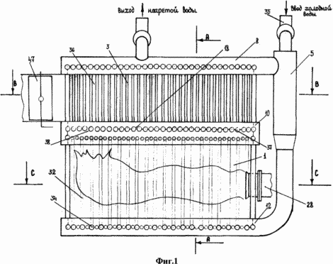
1 shows a sectional boiler, general view
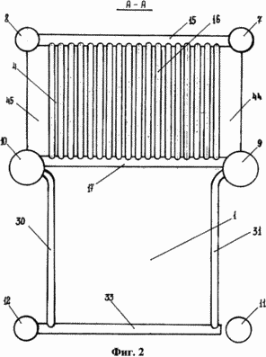
2 - the same section A-A
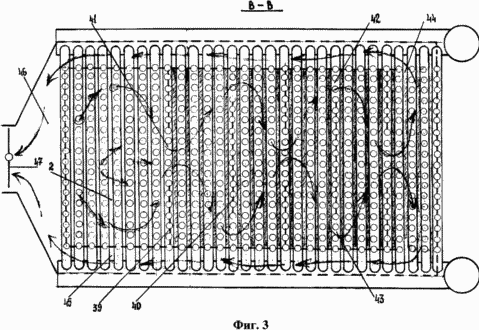
Figure 3 - the same section B-B
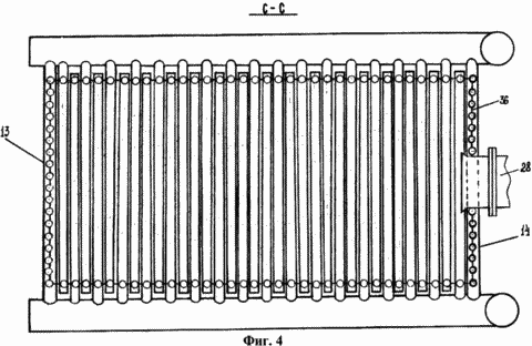
4 - the same section C-C
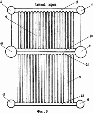
5 - the same rear view
 |
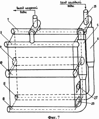 |
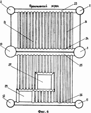
6 - same, front view. 7 - the same layout and collectors ejectors
Sectional boiler contains shielded combustion chamber 1 and placed on it and the message it convective flue 2 camera 3, which is set convective heating surface in the form of parallel sections 4. The boiler has two water-jet ejector 5 and 6 are arranged in pairs, and horizontally longitudinally upper collectors 7 and 8, secondary manifolds 9 and 10 and lower manifolds 11 and 12, which cross-connect section 4, a rear screen 13 and the front screen 14. Each section 4 comprises a series connection of the upper horizontal pipe 15, a series of vertical pipes 16 and average horizontal pipe 17. Section 4 connected to the upper horizontal pipes 15 to the two upper manifolds 7 and 8 and the average horizontal tubes 17 which form the top shield 18, two medium reservoirs 9 and 10. The rear shield 13 includes an upper horizontal pipe 19 connected two upper manifolds 7 and 8, the two horizontal secondary tubes 20 and 21 connected to two secondary manifolds 9 and 10, and a lower horizontal pipe 22 connected to the two lower manifolds 11 and 12. The front shield 14 comprises an upper horizontal pipe 23 connected two upper manifolds 7 and 8, the two horizontal secondary tubes 24 and 25 connected to two secondary manifolds 9 and 10, and a lower horizontal pipe 26 connected to the two lower manifolds 11 and 12. The front shield 14 comprises an opening 27 for the burner 28 and an opening 29 for the manhole. Each of the two side screens 30 and 31 comprises a number of vertical tubes 32, upper ends of which are respectively connected to two secondary manifolds 9 and 10, and the lower ends are connected in pairs, one from each row of horizontal tubes 33, which form the bottom screen 34 and are alternately connected to one ends of the lower one of the headers 11 and 12. two water jet ejector 5 and 6 are connected to a common input of cold water and 35 each connected to one of the two upper manifolds 7 and 8 and to one of the two lower manifolds 11 and 12 to form multiple forced circulation of water. Two upper manifold 7 and 8 are connected to the common terminal of the heated water. The outer surface of the boiler scald spacers 36 between the pipes. The upper screen 18 scald spacers 37 between the pipes to form the opening 38 for flue 2. Section 4 are divided into groups of 39 and welded spacers 40 alternately repeating the formation of the central gas duct 41 and two side flues 42 and 43, the latter of which are connected to the outer side 44 and gas ducts 45 a back boiler in a side flue 46, wherein the rotary damper 47 is installed.
BOILER WORKS AS FOLLOWS
The combustion of fuel in the furnace 1, the gases pass the opening 38 in the convection chamber 3, pivoting at this 180 °, and further through the section 4 convection part, making thus zigzag movement through the central gas duct 41 and the side flues 42 and 43, reaching a maximum of heat transfer and uniform heat transfer. With the passage of convection chamber 3 due to the intensive heat and gases are cooled by passing through the outer side flues 44-45, includes a common gas duct 46 in which a rotary slide valve for adjusting the boiler draft. The cold water enters the boiler through the pipe 35 and is supplied to the lower headers 11 and 12 through a pair of jet pumps 5 and 6, then through the lower horizontal pipe 33 of the screen rises, heating by side screens 30 and 31 in the middle collectors 9 and 10. Of the medium distributing manifolds 9 and 10 the water enters further into the upper screen 18 and, passing through the vertical pipes 16 of the convective part is fed into the upper manifolds 7 and 8, where a part of the hot water re-enters the jet pumps 5 and 6, mixed with incoming into the boiler cold water and part of the hot water is directed through the outlet to the consumer. In this operation provides multiple jet pump forced circulation of water inside the boiler which increases the efficiency of the heating surfaces and, consequently, increases the efficiency of the boiler.
The invention eliminates the disadvantages of the two above-described samples sectional boilers due to the fact that:
- Heating water introduced through the jet pump to the lower nozzle headers only and promotes natural circulation of the water inside the boiler when it is heated; by ejection by means of jet pumps made multiple forced circulation of water inside the boiler, a manifold increase in water velocity inside the boiler and reducing the likelihood of the formation of sludge in the heating surfaces;
- Vertical tubes of the side screens 30 and 31 are at the top of bends that reduces the hydraulic resistance of the boiler and reduces the probability of slagging in comparison with the rectangular flue screens;
- The presence of the manhole 29 in the combustion chamber 1 allows for inspection of the inside space of the boiler;
- Boiler maintainable and easy to use, any replacement of the failed section requires minimal effort due to the fact that it is free to be cut off from the reservoir and replaced by a new, directly in the boiler room;
- Boiler gazoploten, the outer surface of the boiler scald spacers between the pipes, which eliminates the heavy lining of the outer part and replace light quick heat-insulating mats;
- A distinctive feature of the boiler design is the design of its flue pipes with an opening between the firebox and the convection part and a zig-zag path of passage of the combustion products at the expense of a certain way of welded spacers between the vertical tubes of the convective sections alternate form of repeating the central gas duct and two side flues, the last of which is connected to the outer side gas ducts for the rear screen in a flue.
CLAIM
A sectional boiler comprising shielded combustion chamber and placed on it and the message it flue convection chamber in which is installed a convective heating surface in the form of parallel sections, characterized in that it contains two water-jet ejector and arranged in pairs, horizontally and longitudinally upper , middle and lower headers, which laterally connected sections, rear and front screens, each section comprises a series-connected upper horizontal tube, a number of vertical tubes and a middle horizontal pipe sections connected upper horizontal tubes in the two upper headers, and the average horizontal tubes that form the upper screen, two medium reservoirs, rear screen, front screen include upper horizontal pipe, two middle horizontal pipe, a series of vertical tubes and a lower horizontal pipe, rear and front screens connected to the upper horizontal tubes to the two upper reservoirs, the average horizontal pipes to two medium reservoirs, the lower horizontal tubes in the two lower manifolds, front screen further comprises a rectangular opening for the manhole, each of the two side screens comprises a number of vertical tubes, the upper ends of which are respectively connected to two secondary collectors, while the lower ends are connected in pairs, one of each row, the horizontal tubes that make up the lower screen and which are alternately connected to one ends to one of the two lower manifolds, two ejectors coupled to a common input of cold water and connected each to one of the two upper manifolds and one of the two lower manifolds with the formation of multiple forced circulation of water, the top two collector connected to a common output of hot water, the outer surface of the boiler scald spacers between the pipes, the top screen scalded spacers between the pipes to form the opening for the flue pipe, convective sections divided into groups welded spacers between the pipes with alternate form of repetitive central gas duct and two side flues, the last of which is connected to the outer side of the rear side-pass boiler in a gas duct in which a rotary slide valve for adjusting the draft.
print version
Publication date 28.01.2007gg


Comments
Commenting, keep in mind that the content and the tone of your messages can hurt the feelings of real people, show respect and tolerance to his interlocutors, even if you do not share their opinion, your behavior in terms of freedom of speech and anonymity offered by the Internet, is changing not only virtual, but real world. All comments are hidden from the index, spam control.