| section Home
Production, Amateur Radio amateur Model aircraft, rocket- Useful, entertaining |
Stealth master
Electronics Physics Technologies invention |
space Mystery
Earth Mysteries Secrets of the Ocean Stealth section Map |
  |
| Use of material is permitted for reference (for websites - hyperlinks) | |||
Navigation: => |
Home / Products Patents / In the section of the catalog / back / |
|
INVENTION
Russian Federation Patent RU2152565
![]()
METHOD OF ELECTRIC HEATING FLUID FLOW
AND DEVICE FOR ITS IMPLEMENTATION
Name of the inventor: Kazan AM .; Zavorin AS .; Makeev AA .; Yuzhaninov EG
The name of the patentee: Kazan Anatoly; Zavorin Alexander; Anatoly Makeev; Yuzhaninov Eugene G.
Address for correspondence: 630075, Novosibirsk, st. Alexander Nevsky 6 kv.37, Yuzhaninova EG
Starting date of the patent: 1998.11.19
Method and apparatus for electrically heating fluids intended for use in heating systems of residential and industrial buildings as a backup heat these systems. The device comprises a housing with inlet and outlet pipes, within which the heating element is concentrically mounted on the grooved outer surface and a collector with holes in the side of the heating element. The device can be performed in single-phase and three-phase embodiment. The heated liquid is fed into the reservoir and an electrical heater through its perforations a flow directed radially heating element body, washing the surface. Speed aimed at heating the flow element is set longer sredneraskhodnoy rate in the volume of the device in the space defined by the collector and the heating element, providing nucleate boiling of the liquid in the groove of the heating element and the removal of bubbles beyond it, at the expense of the fluid in the groove is not formed dry spots that It prevents the formation of scale.
DESCRIPTION OF THE INVENTION
The invention relates to teplotehnihi art and can be used for hot water heating systems of residential and industrial buildings, including a backup heating of these systems.
Known fluid flow heating method by direct contact of liquid with a heating element disposed within the housing, is implemented in various known devices. For example, in a tubular heater fluid (US patent N 5396574, 1992, F 24 H 1/10) in which the heated liquid is fed into the housing, designed as a coil and is heated by directly contacting the electric resistance heating elements, the configuration of the body . A and the electric heater (UK patent N 2270370, 1994 g., F 24 H 1/10), in which incoming liquid into the barrel heats U-shaped heating elements.
However, in this method, implemented as described devices, the liquid contacting with the heating elements causes high scale formation on the surface of the heating elements, which reduces their heat transfer and fluid heating unevenness in the screen housing reduces the efficiency of the process and, accordingly, its implementing device.
Known method of heating fluid flow described in the author. St. USSR N 1041823, F 24 H 1/20, 1983, in which the method for increasing the effectiveness of providing more uniform heating throughout the volume of the fluid through radial electric heater supply heated fluid flow uniformly over the entire height of the housing.
The method is implemented in electric apparatus comprising a cylindrical housing with a coaxially disposed collector having vertical rows of holes. The heating element is a set of plates arranged radially between the collector rows of holes.
However, these solutions do not provide a significant reduction in scale formation and require additional measures to pre-treatment of the heated water.
The closest in technical essence to the claimed method is a liquid heating and realizes his device described in SU, USSR N 1651049, F 24 H 1/20, 1991 g.
According to the method the heated liquid is fed into the manifold of the electric heater form a radially directed flow from the reservoir to the heating element, uniformly washing its surface, and a heated liquid is supplied to the consumer.
The device realizing this method comprises a housing with inlet and outlet nozzles disposed in the housing coaxially with it manifold perforations covering the heating element.
The disadvantage of these technical solutions is their low efficiency due to the still considerable amount of scale deposited on the heating element, although the scaling process is slowed more than in the examined analogs. This is due to deterioration in the total mass transfer fluid compared with the previously discussed analogs.
The task to be solved by the claimed invention, a method of heating the flow of liquid and a device for its implementation, provides high efficiency by reducing scale formation without pre-cleaning fluid to be heated.
The task performed in the process of electrically heating the flow of liquid, consists in that the heated liquid is fed to the collector of the electric heater and through its perforations stream is directed into the housing radially heating element, washing its surface, and a heated liquid is withdrawn from the heater according to the invention, the rate of directional the heating element of the flow rate is set higher sredneraskhodnoy in the total device, forming a zone of increased circulation in the space defined by the collector and the heating element, providing nucleate boiling liquid in the groove of the heating element and the removal of bubbles beyond.
To implement this method in a device for heating the flow of fluid, comprising a housing with inlet and outlet pipes, within which is concentrically mounted heating element and the manifold holes, according to the invention, the heating element has a groove on the outer surface and the openings collector face the heating element.
When the device in a single-phase embodiment, the heating element is located on the axis of the device and the collector is in the form of at least three tubular elements disposed around the heating element on a circle concentric casing at an equal distance from each other.
When the device in a three phase embodiment, the collector is located on the axis of the device, and the heating element is in the form of at least three tubular elements disposed around the circumference of the collector of concentric casing at an equal distance from each other.
 |
 |
 |
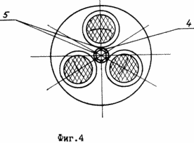 |
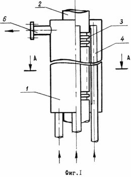
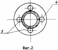
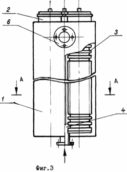
BRIEF DESCRIPTION OF THE DRAWINGS FIG. 1 is a perspective view of the electric heater (single version); FIG. 2 - a section along A-A of the electric heater; FIG. 3 - three-phase version of the electric heater; FIG. 4 - section along A-A of the three-phase electric heater.
The method is implemented in a device which comprises a housing 1, a cylindrical body coaxial tubular heating element 2, on the outer surface of which grooves 3 are made, for example, horizontal or helical. Manifold 4 has a number of openings 5 spaced along the pipe and facing the heating element 2. The holes 5 can be formed as a continuous slot or aperture set. The housing 1 is provided with outlet pipes 6.
Implementation of the method of heating the liquid flow is illustrated by the work of the electric heater.
The liquid to be heated is supplied through a supply pipe (not shown in the drawing) into the manifold through the openings 4 and 5 in the body 1 is directed radially to the heating element 2. As a result of intensive heating of fluid in the groove 3 of the heating element 2 occurs vaporization. Bubbles liquid filling bore, as it were running on it, driven by flowing around the heating element radial flow. Due to this movement in the groove is not formed dry spots, which prevents the formation of scale. The flow of liquid bubbles are removed from the grooves and condense in the total volume of liquid. During the heating process between the commutator 4 (on the location of holes 5) and the heating element 2 (two to three grooves) formed annular zone active circulation, which occurs due to removal of scale-forming substances in a total volume of liquid. The liquid temperature throughout the volume of the body quickly leveled and heated fluid moves the output to a discharge pipe 6.
Using the proposed method and device for its implementation option provides a more efficient flow of fluid heating process, which makes it possible to use, for example in water heating networks without pretreatment (cleaning). In addition, it increases the product life cycle to the planned preventive cleaning.
These solutions can be widely used in heating systems total heat supply of residential and industrial buildings, including as a backup heating, but also for heating and water supply systems for individual use, such as boarding houses, recreation centers.
CLAIM
1. A method of electrically heating the fluid flow, consists in the fact that the heated liquid is fed into the reservoir, is formed on the radially directed flow from the reservoir heating element along its length and the heated liquid output from the apparatus, characterized in that the set of radially directed flow velocity greater sredneraskhodnoy speed devices in total, an elevated area forming a circulation between the collector and the heating element providing nucleate boiling liquid and the removal of bubbles outside the heating element.
2. The apparatus for heating a liquid flow, comprising a housing with inlet and outlet pipes, which is concentrically mounted within a heating element and a collector with a number of holes along its length facing said heating element, characterized in that the heating element has a groove on the outer surface.
3. Apparatus according to claim 2, characterized in that the heating element is disposed on the axis of the device and the collector is in the form of at least three tubular elements disposed around the heating element on a circle concentric casing at an equal distance from each other.
4. Device according to claim 2, characterized in that the collector is located on the axis of the device, and the heating element is in the form of at least three tubular elements disposed around the circumference of the collector of concentric casing at an equal distance from each other.
print version
Publication date 29.01.2007gg
![]()

Comments
Commenting, keep in mind that the content and the tone of your messages can hurt the feelings of real people, show respect and tolerance to his interlocutors, even if you do not share their opinion, your behavior in terms of freedom of speech and anonymity offered by the Internet, is changing not only virtual, but real world. All comments are hidden from the index, spam control.