
| Start of section
Production, amateur Radio amateurs Aircraft model, rocket-model Useful, entertaining |
Stealth Master
Electronics Physics Technologies Inventions |
Secrets of the cosmos
Secrets of the Earth Secrets of the Ocean Tricks Map of section |
  |
| Use of the site materials is allowed subject to the link (for websites - hyperlinks) | |||
Navigation: => |
Home / Patent catalog / Catalog section / Back / |
|
INVENTION
Patent of the Russian Federation RU2238483
![]()
HEATING UNIT
The name of the inventor: Mushtai Ivan Stepanovich (UA); Babich Nikolai Vasilyevich (UA)
The name of the patent owner: Mushtai Ivan Stepanovich (UA); Babich Nikolai Vasilyevich (UA)
Address for correspondence: 02166, Kiev, Prospect Lesnoy, 33, kv.385, E.P. Yushchenko
Date of commencement of the patent: 2001.04.13
The invention is intended for use in heat power engineering, namely in water heating systems for heating systems of houses, structures and living quarters. The heating device has a housing with a water jacket that covers the furnace and flue gas, a heat exchanger in the form of a pipe block with rectangular or square cross-sections with turbulators is placed in the upper part of the heating device, the difference between the areas in the section of the heat exchanger and turbulator tube in relation to the cross-sectional area Gas outlet pipe is 1.2-1.6, turbulators are freely inserted into the tubes on the rods with the number of elements from 2 to 12, and the elements of the turbulators are placed at an angle of 90º to the flow of combustion gases. The invention makes it possible to increase the intensity of heat exchange, reduce the temperature of waste gases, simplify the cleaning of surfaces from the deposits of combustion products, ensure the simplicity of the manufacturing technology, reduce the material consumption, simplify the design and increase the efficiency of the heating apparatus.
DESCRIPTION OF THE INVENTION
The invention relates to heat power engineering, namely water heating systems for heating systems of houses, structures and living quarters.
A well-known water-heating boiler selected for the prototype (patent UA No. 24492, class F 24 H 1/22, F 24 H 1/32, published on 30.10.98) has a combustion chamber in which heat exchange sections are inserted which form between And a collector connected to the heat exchange sections located in the lower part of the combustion chamber and having in cross section the shape of rectangular triangles along the edges and isosceles between them and the flue on the exit side of the convective gases has the form of a trapezium, And the dispensing manifold is made in the form of a box, the lateral part of which is the base of the heat exchange sections, and the collector itself is connected in parallel to the general system of the boiler.
The drawback of this boiler is that placing the heat exchange sections very close to the burner will facilitate the contact of the flame of the burner with the sections of the heat exchanger and lead to incomplete combustion of natural gas, a decrease in the boiler's efficiency, and a significant formation of combustion products residues. In addition, the cleaning of the heat exchanger sections from the combustion products is complicated, and there are difficulties in the technology of manufacturing the boiler. The drawbacks are that the sections of the boiler are made in the form of rectangular triangles along the edges and isosceles between them and do not provide an uniform temperature gradient in the gas flow section, and this does not allow the maximum use of the heat of the exhaust gases.
The invention is based on the task of developing a design of a heating device that allows increasing the heat exchange rate, reducing the temperature of the exhaust gases, simplifying the cleaning of surfaces from combustion products, simplifying the manufacturing process, reducing the material consumption, simplifying the design and increasing the efficiency of the heating apparatus.
The solution of the task is provided by the fact that the claimed heating device has a housing with a water jacket that covers the furnace and flue gas, and according to the invention, a heat exchanger in the form of a tube block with rectangular or square cross tubes with turbulators is placed in the upper part of the heating device, Areas in the section of the heat exchanger tube and turbulator in relation to the area of the gas-discharge pipe branch is 1.2-1.6.
According to the second aspect of the invention, the elements of the turbulators are installed at an angle of 90 ° to the flow of combustion gases, which eliminates the formation of stagnant zones, increases the efficiency of heat transfer, increases the efficiency of the heating apparatus, and reduces its overall dimensions and weight.
According to the third claim, the turbulators on the rods are freely inserted into the heat exchanger tubes in an amount of from 2 to 12, this makes it easy to clean the pipes from the combustion products. In addition, the turbulators, without changing the gas flow rate, increase their path, average the temperature gradient of the flow in the section of each tube of the pipe block and reduce the temperature of the exhaust gases in the chimney of the heating device to 150 ° C.
The presence of these signs allows us to draw a conclusion about the novelty of the claimed solution.
These distinctive features do not flow logically from the current level of development of heating installations for water heating systems for houses, buildings and household premises, but are obtained through creative solutions to the technical problem of the execution of a pipe block and turbulators of a certain shape, their placement in a heating chamber and with each other on an optimal Distance.
The effectiveness and originality of these differences are in close connection with the achievable technical result.
The simplicity of the shape of the tube block and turbulators makes the design of the heating device simple in production.
In comparison with the prototype, the claimed solution allows:
- increase the intensity of heat transfer;
- increase efficiency;
- reduce costs of gas fuel;
- reduce the material consumption;
- simplify the design of the heat exchange unit in comparison with the heat exchanger sections, which have the shape of different triangles in the section;
- to ensure the simplicity of the manufacturing technology;
- reduce the temperature of the flue gases in the chimney to 150 ° C;
- to simplify the cleaning of surfaces from the deposits of combustion products.
Possible practical implementation of such a design of the heating system allows us to conclude that it meets the criterion of "industrial suitability".
 |
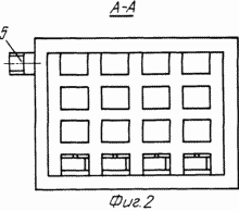 |
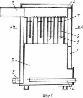
1 shows a view of a heating apparatus; FIG. 2 is a sectional view of the AA of FIG. 1. FIG.
The heating apparatus (FIG. 1) is a steel welded body 1, the upper part of which is covered with a removable cover 2, a chimney 3 is installed on the rear wall of the case, and a gas burner 4 is located in the bottom of the furnace. 4. The space between the outer and inner walls of the housing is filled with water. On the rear wall of the body are welded pipes 5, 6, which connect the heating system to the heating system. In the middle of the case, in its upper part there is a tube block 7 with tubes of rectangular cross-section, in tubes of which 8 turbulizers 9 are inserted on the removable rods 8, which increase the coefficient of heat transfer from gases to the heat carrier (water).
The heating apparatus (FIG. 1) operates as follows. Gas fuel is supplied to the burner 4, which is located in the furnace 10 of the heating apparatus (FIG. 1). In the process of combustion of gas fuel, the generated heat energy is transferred to the heat carrier by light radiation on the side and top walls of the furnace, which are located at the maximum allowable distance from the burner flame, and the combustion products that enter the pipe block 7 with rectangular tubes with installed in them on removable Rods by turbulators 9.
The construction of the tube block and the geometric dimensions of the turbulators ensure the formation of a turbulent flow with effective transfer of thermal energy to the heat carrier (water), eliminate the formation of stagnant zones, increase the efficiency of the heating apparatus.
The combustion products are vented through the chimney 3, which is located in the rear wall of the heating device (Fig. 1).
CLAIM
1. A heating apparatus which has a housing with a water jacket that encloses a furnace and flue, characterized in that a heat exchanger in the form of a tube block with rectangular or square cross-section tubes with turbulators is located in the upper part of the heating device, the difference between the areas in the pipe section Heat exchanger and turbulator in relation to the sectional area of the gas outlet pipe is 1.2-1.6.
2. A heating apparatus according to claim 1, characterized in that the elements of the turbulators are located at an angle of 90 ° to the flow of combustion gases.
3. A heating apparatus according to claim 2, characterized in that the turbulators on the rods with a number of elements from 2 to 12 are freely inserted into the pipes.
print version
Date of publication 29.01.2007gg
![]()

Comments
When commenting on, remember that the content and tone of your message can hurt the feelings of real people, show respect and tolerance to your interlocutors even if you do not share their opinion, your behavior in the conditions of freedom of expression and anonymity provided by the Internet, changes Not only virtual, but also the real world. All comments are hidden from the index, spam is controlled.