| Start of section
Production, amateur Radio amateurs Aircraft model, rocket-model Useful, entertaining |
Stealth Master
Electronics Physics Technologies Inventions |
Secrets of the cosmos
Secrets of the Earth Secrets of the Ocean Tricks Map of section |
|
| Use of the site materials is allowed subject to the link (for websites - hyperlinks) | |||
Navigation: => |
Home / Patent catalog / Catalog section / Back / |
|
INVENTION
Patent of the Russian Federation RU2148754
![]()
LIQUID HEATING COOLER
The name of the inventor: Elin Boris Viktorovich; Terekhin Vyacheslav Vasilyevich
The name of the patentee: Elin Boris Viktorovich; Terekhin Vyacheslav Vasilyevich
Address for correspondence: 141070, Moscow Region. City of Korolev, st. Tsiolkovsky 10, ap. 41, Elin BV
Date of commencement of the patent: 1998.07.23
The invention relates to heating engineering and can be used in heating and heating systems for liquids, as well as for mixing liquids in various technological processes. The liquid heat generator comprises a housing with an inlet nozzle and a twist chamber connected to the housing with tangential holes and an outlet nozzle. The twist chamber with the exit nozzle is made of a two-sheeted type in the form of two concentrically located one-in-one rolling chambers, each with its outlet nozzle, with the liquid in the chambers being twisted in opposite directions. The technical result is to increase the heat generation and efficiency of mixing liquids, reduce the metal consumption and the cost of a liquid heat generator.
DESCRIPTION OF THE INVENTION
The invention mainly relates to heat engineering and can be used in various heating systems, as well as for heating liquids for industrial and domestic needs.
The invention can also be used for mixing and preparing emulsions of liquids under various technological processes.
Known are devices using changes in fluid parameters (pressure, flow velocity) to produce heat energy or mixing liquids, see, for example, an injector jet mixer, application 95117191/20 17.10.95 (patent 3563 U1), a heat generator and a heating device Liquids under the application 93021742/06 26.04.93 (patent RU 2045715 C1).
The mixer according to the application 95117191/20 comprises a mixing chamber, a homogenization chamber with an outlet nozzle and a continuous partition with blades at the periphery arranged perpendicularly to the liquid flow in the exit nozzle of the homogenization chamber.
The mixing chamber is made in cross-section in the form of a spiral and is provided with two fluid supply holes: in the side wall for feeding into the spiral part and in the end wall for approach along the axis of the chamber.
This mixer does not provide sufficient fineness of mixing of liquids, since a continuous baffle with blades on the periphery has a small length in the direction of flow of liquid, and the supply of one liquid to the mixing chamber is made through the hole in the end wall along the axis of the mixing chamber without twisting.
The heat generator according to patent application 93021742/06, patent 2045715 contains a cyclone (a twist chamber) and a cylindrical body connected thereto with a brake device in the form of several ribs radially disposed on the central bush.
Disadvantages of this heat generator are the considerable dimensions, and consequently, the metal consumption and cost caused by the long length of the cylindrical body of the heat generator, and insufficiently full utilization of the energy of the moving fluid due to the adopted design of the braking device.
The heat generator and the device for heating liquids according to the application 93021742/06, patent 2045715 are adopted as the closest to the invention in terms of the set of essential features of the technical solution - the prototype.
The aim of the invention is to increase the efficiency of liquid heating and mixing of liquids, to reduce the metal consumption and the cost of a liquid heat generator.
The task is solved using the combination of the following essential features.
The liquid heat generator comprises a housing with an inlet nozzle and a twist chamber connected to the housing with tangential holes and an outlet nozzle.
The liquid is pumped by the electric pump into the inlet hose of the housing, through the tangential holes it gets into the twist chamber, accelerates, gets rotary motion and enters the exit nozzle.
Distinctive features of the invention are:
- the twist chamber with the exit nozzle is made of a two-sheeted type in the form of two concentrically located co-rotating chambers each with its outlet nozzle;
- the outer diameter of the inner spinner chamber is made equal to or less than 0.9 (D-2d),
Where D is the internal diameter of the outer twist chamber;
D is the diameter of the tangential openings of the outer twist chamber, and the outer diameter of the outlet nozzle of the inner spinner chamber is made equal to or smaller than 0.7 of the inner diameter of the outlet nozzle of the outer twist chamber;
- the end face of the exit nozzle of the inner twist chamber is located inside the outlet nozzle of the outer twist chamber at a distance from the end face of the outlet nozzle of the outer twist chamber equal to or greater than 1.5 inner diameter of the outlet nozzle of the inner twist chamber;
- the tangential openings of the inner twist chamber and the tangential openings of the outer twist chamber are directed in opposite directions;
- the body with the inlet branch pipe is made of two-cavity in the form of two concentrically arranged one-in-another bodies each with its own inlet branch, the cavity of the inner case being connected to the cavity of the inner spinner chamber and the cavity of the outer casing being connected to the cavity of the outer scroll chamber.
The execution of a liquid heat generator with the indicated distinctive features allows:
- increase heat generation and mixing efficiency of liquids by providing, in the applied design of the liquid heat generator, the interaction on the inner wall of the exit nozzle of the outer chamber of twisting of the two fluid streams having a twist in opposite directions;
- reduce the length of the length of the liquid heat generator due to the fact that the twist chamber with the outlet nozzle is made of a two-sheeted type in the form of two concentrically located one-in-one roll-up chambers each with its outlet nozzle and the interaction of two liquid streams having the opposite direction of twist on the inner surface of the outlet nozzle The outer chamber of twist, and consequently, reduce the metal consumption and the cost of the liquid heat generator;
- separate supply of different liquids due to the fact that the body with the inlet branch pipe is made of two-cavity in the form of two concentrically arranged one in the other bodies each with its own inlet branch, the cavity of the inner case being connected to the cavity of the inner spinner chamber and the cavity of the outer case connected to the outer cavity Camera twist.
 |
 |
 |
 |
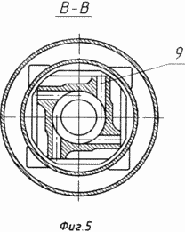 |
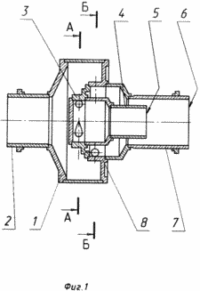
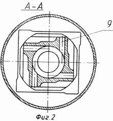
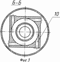
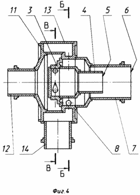
In Fig. 1 is a general view of a liquid heat generator with a variant of a single-cavity body; FIG. 2 is a sectional view of the liquid heat generator according to the tangential openings of the inner twist chamber, FIG. 3 is a sectional view of the liquid heat generator according to the tangential holes of the outer twist chamber, FIG. 4 is a perspective view of a liquid heat generator with a variant of a two-lined housing; FIG. 5 is a sectional view of a liquid heat generator with a two-cavity body along the tangential holes of the inner twist chamber. A liquid heat generator, see FIG. 1, 2, 3, comprises a body 1 with an inlet nozzle 2 and a twist chamber connected to the body with tangential holes and an outlet nozzle. |
The twist chamber is made of two-cavity in the form of two concentrically located co-rotating chambers each with its outlet nozzle:
- the inner chamber of the twist 3 with the output nozzle 4;
- External twist chamber 8 with outlet nozzle 7.
In a liquid heat generator with a variant of a two-cavity housing, see FIG. 4, 5, the body with the inlet branch pipe is made of two-cavity in the form of two concentrically arranged one in the other bodies each with its own inlet branch:
- the inner case 11 with the inlet branch pipe 12;
- the outer shell 13 with the inlet branch pipe 14.
The cavity of the inner body 11 is connected to the cavity of the inner scroll chamber 3 and the cavity of the outer casing 13 is connected to the cavity of the outer scroll chamber 8.
The outer diameter of the inner spinner chamber 3 is made equal to or less than 0.9 (D-2d),
Where D is the inner diameter of the outer twist chamber 8;
D is the diameter of the tangential holes 10 of the outer roll chamber 8,
And the outer diameter of the outlet nozzle 4 of the inner spinner chamber is made equal to or smaller than 0.7 of the inner diameter of the outlet nozzle 7 of the outer scroll chamber 8.
The end 5 of the outlet nozzle 4 of the inner spinner chamber 3 is located inside the outlet nozzle 7 of the outer scroll chamber 8 at a distance from the end 6 of the outlet nozzle 7 of the outer scroll chamber 8 equal to or larger than 1.5 of the inner diameter of the outlet nozzle 4 of the inner scroll chamber 3.
The tangential openings 9 of the inner spinner chamber 3 and the tangential holes 10 of the outer scroll chamber 8 are made directed in opposite directions.
When the liquid heat generator operates with a variant of a single-cavity housing, the liquid is supplied by an electric pump through the inlet branch pipe 2 into the housing 1.
In the housing 1, the liquid flow is divided into two streams:
- the first flow of liquid through the tangential holes 10 enters the external scroll chamber 8, gets a twist in a plane perpendicular to the longitudinal axis of the heat generator and is output to the outlet nozzle 7;
- the second flow of liquid through the tangential holes 9 enters the inner scroll chamber 3, gets a twist in a plane perpendicular to the longitudinal axis of the heat generator and is discharged into the exit nozzle 4, the direction of the twist of the liquid flow in the inner chamber opposite to the direction of the fluid flow in the outer chamber, That the tangential openings of the inner twist chamber and the tangential openings of the outer twist chamber are directed in opposite directions.
When the liquid heat generator works with a variant of a two-cavity housing:
- one liquid is supplied by an electric pump through the inlet branch 14 to the outer casing 13, enters through the tangential holes 10 into the outer scroll chamber 8, gets a twist in a plane perpendicular to the longitudinal axis of the heat generator and is discharged into the outlet nozzle 7;
- another liquid is supplied by an electric pump through the inlet pipe 12 to the inner housing 11, enters through the tangential holes 9 into the inner scroll chamber 3, gets a twist in a plane perpendicular to the longitudinal axis of the heat generator and is discharged into the outlet nozzle 4.
The implementation of the inner scroll chamber 3 and the outlet nozzle 4 and the outer scroll chamber 8 and the outlet nozzle 7 with the above dimension ratio makes it possible to place the inner chamber with the outlet nozzle inside the gas vortex formed when the liquid flow in the outer chamber is twisted, without disturbing the flow process Liquid through the outer chamber and the outlet nozzle of the outer chamber.
When the flow of liquid passing through the inner chamber 3 is reached, the end 5 of the outlet nozzle 4 located inside the exit nozzle 7 of the outer scroll chamber 8 at the above-mentioned distance from the end face 6 of the outlet nozzle of the outer twist chamber, the liquid flow is pushed out to the periphery by centrifugal forces, .e. On the inner surface of the outlet nozzle 7, through which the flow of liquid from the outer twist chamber flows.
In the interaction on the inner surface of the exit nozzle 7 of the outer chamber of twist 8 of the two fluid streams having the opposite direction of twist, there is mutual introduction, sudden braking and intensive mixing of the liquid flows with the release of heat due to changes in the kinetic energy of the fluid streams.
The twisting of the two fluid streams in the opposite direction in the inner and outer twist chambers and their subsequent interaction on the inner surface of the exit nozzle of the outer twist chamber, provided by the design of the liquid heat generator, increase heat generation and mixing efficiency of liquids during operation of the liquid heat generator.
The implementation of a twist chamber with a two-cavity outlet nozzle in the form of two concentrically-spaced twist chambers each with its outlet nozzle and ensuring the interaction of the two fluid streams having the opposite twist direction on the inner surface of the outlet nozzle of the outer twist chamber allows to reduce the length of the liquid heat generator, Consequently, reduce the metal consumption and the cost of the liquid heat generator.
In accordance with the essence of the invention, prototypes of a liquid heat generator were manufactured and tested. Positive test results were obtained.
CLAIM
A liquid heat generator comprising a housing with an inlet pipe and a twist chamber connected to the housing with tangential holes and an outlet nozzle, characterized in that the twist chamber with the outlet nozzle is made of a two-sheeted type in the form of two concentrically located co-rotating chambers, each with its outlet nozzle .
2. Liquid heat generator according to claim 1, characterized in that the outer diameter of the inner spinner chamber is equal to or less than 0.9 (D-2d), where D is the inner diameter of the outer twist chamber; D is the diameter of the tangential openings of the outer twist chamber, and the outer diameter of the outlet nozzle of the inner spinner chamber is made equal to or smaller than 0.7 of the inner diameter of the outlet nozzle of the outer twist chamber.
3. The liquid heat generator according to claim 1, characterized in that the end of the outlet nozzle of the inner spinner chamber is located inside the outlet nozzle of the outer twist chamber at a distance from the end face of the outlet nozzle of the outer scroll chamber of equal to or greater than 1.5 inner diameter of the outlet nozzle of the inner twist chamber.
4. The liquid heat generator according to claim 1, characterized in that the tangential openings of the inner twist chamber and the tangential openings of the outer twist chamber are directed in opposite directions.
5. The liquid heat generator according to claim 1, characterized in that the body with the inlet nozzle is made of a two-cavity in the form of two concentrically arranged one in the other bodies, each with its own inlet branch, the cavity of the inner case being connected to the cavity of the inner spinner chamber, and the cavity of the outer shell Is connected to the cavity of the outer twist chamber.
print version
Date of publication 29.01.2007gg


Comments
When commenting on, remember that the content and tone of your message can hurt the feelings of real people, show respect and tolerance to your interlocutors even if you do not share their opinion, your behavior in the conditions of freedom of expression and anonymity provided by the Internet, changes Not only virtual, but also the real world. All comments are hidden from the index, spam is controlled.