
| Start of section
Production, amateur Radio amateurs Aircraft model, rocket-model Useful, entertaining |
Stealth Master
Electronics Physics Technologies Inventions |
Secrets of the cosmos
Secrets of the Earth Secrets of the Ocean Tricks Map of section |
  |
| Use of the site materials is allowed subject to the link (for websites - hyperlinks) | |||
Navigation: => |
Home / Patent catalog / Catalog section / Back / |
|
INVENTION
Patent of the Russian Federation RU2079056
![]()
TEPLOGENERATING INSTALLATION "TGU-1"
The name of the inventor: Vadim Igorevich Bespalov; Natalia Anatolievna Strahova; Mikhail Shitov; Dzyuba Vladimir Konstantinovich
The name of the patent owner: Bespalov Vadim Igorevich ; Natalia Anatolievna Strahova; Mikhail Shitov; Dzyuba Vladimir Konstantinovich
Address for correspondence:
The effective date of the patent: 1994.03.24
Use: in the field of heat generation in the housing and communal services and in any industry to heat the heat transfer fluid. SUMMARY OF THE INVENTION: an installation includes a storage tank with central heating element, a spiral-wound heat-receiving evaporator framing the heating element, and a hot and cold water separator. The heating element is made in the form of a vortex cylindrical tube with tangential input and unidirectional screw threading on the inner surface of the tube.
DESCRIPTION OF THE INVENTION
The invention relates to the generation of heat in an environmentally friendly manner and can be used in the housing and communal services and in any industry for the heating of a liquid coolant.
An adiabatic vortex air tube is known, which includes a cylindrical body, a tangential nozzle inlet, a choke, a diagram, nipples for cold and thermal air (Refrigerators M. Light and Food Industry, 1982. p. 190).
An air generator of cold (heat) is known, which includes a chamber, a nozzle inlet tangential to it, nozzles for the output of cold and thermal air (A.Kholmskaya, Vortex coolers, or cold in batches.) Inventor and rationalizer M. 1990, No. 5, p. 9).
A heat supply system is known that includes a heat pump, an evaporator, a condenser and a gas flue with the first and second heat exchangers installed in it with inlet and outlet pipelines connected to the heat network. In this case, the second heat exchanger is equipped with interconnected sprinklers and a pallet (AS 1449779, b.1, 1989).
The closest to the technical essence and achieved effect is the heat pump system, which contains a heat receiver-evaporator, a separator, a compressor, a pump, a technological heat receiver-condenser, connecting steam lines, drainage lines that form the circulation circuit of the working fluid, and a process heat receiver and a purge water receiver (a. P. 1643893, bulletin 2, 1988).
However, the use of known devices does not allow achieving a relatively high efficiency of the heat generation process, since it is based on the preliminary allocation of the internal energy of the fuel to be burned, then transferred to its heat carrier, and does not directly use the internal open energy of the coolant itself (water).
The essence of the invention consists in that the installation includes a storage tank with a heating element installed in it on the central axis, made in the form of a vortex cylindrical tube with a tangential input of the heat carrier and a screw thread unidirectional with it on its inner surface, a spiral-wound evaporator receiver, A heating element, and a hot and cold water separator.
 |
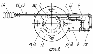 |
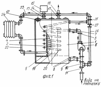
In Fig. 1 shows a general view of the installation on the side with a local size; FIG. 2 the same view from above.
Installation "TGU-1" consists of a tank-accumulator 1 with installed in it coaxially with a heating element 2, made in the form of a vortex cylindrical tube with a tangential input 3 and screw thread 4, which is a continuation of the tangential input 3. Between the bottom of the accumulator tank 1 and the heating Element 2 is a separator 5 for cold and hot water. The separator 5 is made in the form of a perforated horizontally installed partition. The tangential input 3 of the heating element 2 is connected to the pump discharge pipe 6 by the conduit 7. The suction connection of the pump 6 is connected to the outlet pipe 8 of the accumulator tank 1 by a pipe 9 having a cut-in to the make-up pipe 10. The outlet pipe 8 is located between the separator 5 and the bottom Battery tank 1. The tank is accumulator 1, tangential input 3 and branch pipe 8, pipelines 7 and 9, and pump 6 form the internal circulating circuit of the plant. An adjustment valve 11 is provided on the conduit 10. The accumulator tank 1 is provided with a hermetically sealed cover 12 having a fitting 13 terminated by a valve 14 for connection to a discharge line 15 from the compressor 16. A fitting 17 is provided on the cover 12 and terminated by a valve 18 for discharging air From the cavity of the accumulator tank 1 when the unit is filled with a coolant.
The heating element 2 at the bottom has openings 19 around the perimetre for discharging the heat transfer medium into the cavity of the accumulator tank 1. A helically wound tubular heat sink-evaporator 20 is coaxially disposed around the heating element 2 in the cavity of the accumulator tank, the free ends of which are connected to the output 21 and the input 22 Branch pipes. The outlet branch pipe 21 is connected by a conduit 23 to a condenser 24 (a heating device) which in turn is connected by a conduit 25 to the inlet branch pipe 22. The pipeline 23 between the outlet branch pipe 21 and the condenser 24 includes a tie-in of the make-up pipeline 26 with a valve 27. The heat receiver evaporator 20 , Branch pipes 21 and 22, conduits 23 and 25, and a condenser 24 form an external circulation circuit.
INSTALLATION WORKS AS FOLLOWING
The pre-installation is filled with water through the external and internal circulation circuits, respectively, by means of the valves 11 and 27 through the make-up pipelines 10 and 26. When the accumulator tank 1 is filled with water, the air inside its cavity is forced out and removed through the union 17 and the valve 18. After filling The water make-up is stopped by closing the valves 11 and 27, and then the pump 6 is turned on.
Cold water from the bottom of the accumulator tank 1 through the outlet pipe 8 and the pipeline 9 by the pump 6 is pumped into the pipeline 7, from which it enters the tangential input 3 of the heating element 2 under pressure.
When entering the heating element 2 under pressure, tangentially, water releases thermal energy by converting a part of its intrinsic internal energy, caused by the appearance of frictional forces between the internal molecular layers of the flow (kinetic and dynamic viscosity). The transformation of internal energy into thermal energy is intensified in the claimed plant due to the execution on the inner surface of the heating element 2 of the screw thread 4, which is simultaneous with the tangential input 3 and is its continuation. The presence of the screw thread 4 allows eliminating local vortices in the cavity of the heating element 2, ordering the flow of the liquid, increasing the contact surface of the liquid and the heating element 2, and consequently increasing respectively the coefficient of friction in the vertical plane (kinematic viscosity coefficient) and in the horizontal plane (dynamic viscosity coefficient ) Due to the organization of friction in the cavity of the heating element 2, not only between the layers of the liquid, but also between the layers of the liquid and the developed solid surface of the heating element 2. An increase in the values of the corresponding friction coefficients leads to an increase in the values of the friction forces themselves, Thermal energy. The use of such a design of the heating element 2 makes it possible to achieve an increase in the effect of molecular separation of the liquid, intensification of the release of thermal energy by converting the kinetic energy of the stream through the internal energy of the coolant without using the fuel combustion process followed by the transfer of heat energy to the heat carrier (water), and hence the efficiency of the installation.
Heated in the element 2, the heat carrier through the openings 19 opens into the cavity of the accumulator tank 1, where the more heated and less heated fluid flows are stratified due to the difference in their densities. At the same time, the more heated layers of liquid rise to the upper part of the accumulator tank 1, flushing the surface of the helically wound tube heat exchanger-evaporator 20 from the outside, and the less heated layers are lowered through the separator 5 to the lower part of the accumulator tank 1. Installing the separator 5 promotes uniform separation of the heated and Less heated areas of the liquid in the storage tank 1, while reducing the likelihood of local temperature changes in the volume of the liquid.
Thus, a continuous circulation of liquid in the internal circuit of the installation is carried out while the pump 6 is continuously operating until the required coolant temperature in this circuit is reached.
The required temperature of the coolant in the internal circuit is ultimately determined by the required temperature at the surface of the condenser 24, which is in the form of a heater, that is, the temperature of the liquid in the external circulation circuit.
When the heat collector of the evaporator 20 is washed with the heated liquid in the storage tank 1, heating of the liquid of the external circulation circuit, in which, as the liquid warms, its natural circulation begins (due to the difference in the densities of the more heated and less heated layers of liquid) through the conduits 23 and 25. The presence of two independent closed circuits in the heat generating plant makes it possible to regulate its temperature regime in a wide range (up to the production of steam in the external circulation circuit). High temperatures and external coolant can be achieved by using compressor 16. At the same time, compressed air from the compressor 16 through the discharge conduit 15 and the valve 14 is supplied to the cavity of the storage tank 1, creating there an excess pressure allowing the heating medium coolant to heat above 100 ° C . C (boiling points at atmospheric pressure) without the boiling of this coolant. The degree of compression in the cavity of the storage tank 1 determines the parameters of the superheated coolant in the internal, and therefore in the external circulation circuit.
Since the operation principle of the installation is based on the use of only the kinetic energy of the liquid flow and requires only the expenditure of electrical energy, the claimed plant can be considered environmentally friendly, not emitting pollutants to the environment, usually accompanying the combustion process.
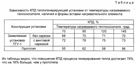
In order to confirm the essentiality of the distinguishing features of the claimed installation, laboratory tests were carried out on the laboratory bench. The test results are tabulated.
CLAIM
Heat generating unit TGU-1, containing a heat receiver-evaporator, separator, compressor, pump, condenser, connecting pipelines forming internal and external circulation circuits, characterized in that the installation includes a storage tank with central heating element installed in it on the central axis. A vortex cylindrical tube with a tangential input and a unidirectional screw threaded on its inner surface, a spiral-wound heat-receiving evaporator framing the heating element, and a separator for hot and cold water.
print version
Date of publication 25.03.2007gg
![]()

Comments
Commenting on, remember that the content and tone of your message can hurt the feelings of real people, show respect and tolerance to your interlocutors even if you do not share their opinion, your behavior in the conditions of freedom of expression and anonymity provided by the Internet, changes Not only virtual, but also the real world. All comments are hidden from the index, spam is controlled.