| section Home
Production, Amateur Radio amateur Model aircraft, rocket- Useful, entertaining |
Stealth master
Electronics Physics Technologies invention |
space Mystery
Earth Mysteries Secrets of the Ocean Stealth section Map |
  |
| Use of material is permitted for reference (for websites - hyperlinks) | |||
Navigation: => |
Home / Products Patents / In the section of the catalog / back / |
|
INVENTION
Russian Federation Patent RU2168121
![]()
process heaters
Name of the inventor: Dobriansky VL .; Zaretsky YV .; Korotkov LV .; Krivosheev AI .; Serazetdinov F.SH .; Serazitdinov R.SH .; Timonin VA
The name of the patentee: State Unitary Enterprise "Aviagaz - Union" (subsidiary KOKB "Union")
Address for correspondence:
Starting date of the patent: 1999.09.14
The invention relates to a device intended for heating of liquids, gases and mixtures thereof, and may be used in various industries for manufacturing processes, for example for heating the natural gas distribution stations on the input. Process heater comprises a burner device, a shell and tube heat exchanger and a shielding outer zone of heat exchanger tubes. Summary of the invention that the entire length of the heat exchanger is placed an additional internal zone shielding tube coaxial outer belt pipes so that the same in structure, length and number of tubes of the outer and inner zones within the furnace volume from the burner are supported in an annular baffle openings fixed to the inner wall of the housing, while the other end - a back plate holes flue duct, wherein the pipe in the radial direction of movement of the heating medium are staggered. Such an arrangement allows the heater to increase its efficiency and reliability while expanding the range of heat loads.
DESCRIPTION OF THE INVENTION
The invention relates to a device intended for heating of liquids, gases and mixtures thereof to provide process efficiency, and may be used in various industries, for example - to preheat the inlet gas distribution stations to prevent hydrate formation process.
Known air heater (see. AS USSR N 567905, cl. The F 24 H 3/08, F 23 D 15/04), containing a burner shell and tube heat exchanger with the radiation section, shielded dense beam of heat exchange tubes, equally spaced from the inner wall of the housing , chimney, entry and exit of heated air collectors.
A disadvantage of the known device is its low efficiency associated with insufficient heat removal only one radiating section, but also - the low reliability and durability of the device as a whole, since the density beam furnace tubes in the actual non-uniformity of heating could cause significant thermal stress on the walls of the pipes subsequent burnout, which entails the need for complete replacement of the heat exchanger.
Known process heater (see. N 98113211/06 application by 06.07.98, at which the decision to grant the patent of the Russian Federation), having burner device, shell and tube heat exchanger, shielded outer belt of heat exchanger tubes, equally spaced with respect to the inner wall of the casing, chimney, entrance collectors and release of the heated medium, and all the heat exchange tubes are inserted one into the other tube, the outer of which is formed with the closed end facing towards the combustion unit, and the other end outside of the flue duct, the working chamber of each of the heat exchange tubes communicated with removable nozzles with inlet and outlet manifolds of the heated medium (the prototype).
Identified in practice, the drawbacks of the process heater is as follows. Firstly, overheating of the casing wall due to its "lighting" of the flame through the gaps between the tubes processing within the radiant section, resulting in the need to use expensive heat-resistant alloy and an outer heat-insulating material. Second, limit the length of the furnace volume by placing in the axial zone of the internal convective bundle of heat exchanger tubes is not possible to increase the heat load of the heater, followed by an increase in range of a torch that led to nedogoraniyu fuel mixture near the dead ends of pipes convective bundle and increase carbon emissions and carbon monoxide beyond acceptable standards. And in - the third, the length of pipe screens and convective beams significantly different, which does not allow to unify the most time-consuming elements of the heat exchanger, and this leads to higher costs for development and manufacture of the heater as a whole.
The aim of the invention is to improve the reliability and efficiency while expanding the range of heat loads, maintaining ecological norms of emissions in the flue gases and reducing the cost of development and manufacture of the heater as a whole.
This aim is achieved in that the entire length of the heat exchanger is placed instead of the internal convective beam teplooobmennyh pipe additional internal zone shielding tube coaxial outer belt pipes so that the same in structure, length and number of tubes of the outer and inner zones within the furnace volume, from burner supported in annular partition holes with fixed internal wall of the casing, and the other end - a back plate holes flue duct, wherein the pipe in the radial direction of movement of the heating medium are staggered. In addition, the axial bottom of the rear, not occupied by tubes, a screen in the form of a cone coaxial with the casing heat exchanger and its vertex facing towards the burner. Thus the length of the furnace volume on the axis of the heat exchanger bounded at one end burner device, the other - screen should be less than the maximum possible value range of a burner flame, and an inner diameter of the annular partition - not less than the diameter of the chimney.
The drawing shows a general view of a process heater in the longitudinal and transverse incisions.
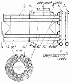 |
A heater comprising a heating medium source, which is, for example, one burner device, a shell and tube heat exchanger and a shielding outer zone 2 of heat exchanger tubes, equally spaced relation to the inner wall of the housing 3, a stack 4, entry 5 and exit manifold 6 of the heated medium. Heat exchange tubes are inserted one into another tube, outside 7 of which are made with the closed end facing towards the burner 1. At the other end, outside the flue box 8, the working chamber of each of the heat exchange tubes communicated with two removable connectors 9 and 10 with collectors input 5 and output 6, respectively. In this case the entire length of the heat exchanger placed additional inner belt 11, the shielding pipe coaxial outer zone 2 of pipes so that the same in structure, length and number of tubes of the outer 2 and inner 11 zones within the furnace volume from the burner 1, supported in holes annular partition 12 fastened to the inner wall of the casing 3, and the other end - the bottom 13 in the rear flue duct openings 8, wherein the pipe in the radial direction of movement of the heating medium are staggered. The paraxial back plate portion 13 not occupied by the tubes, a screen 14 in the form of a cone coaxial with the casing heat exchanger 3 and its apex facing toward the burner 1. At the same length of the furnace volume on the axis of the heat exchanger bounded by one end of one burner device, with another - screen 14 should not be less than the maximum value range of a torch burner 1, and the inner diameter of the annular barrier 12 - not less than the inside diameter of the chimney 4. |
HEATER WORKS AS FOLLOWS
Heated medium, such as purified natural gas from the pipeline enters the inlet manifold 5 through nozzles 9 - in the annular gaps of heat exchanging tubes of both belts 2, 7, 11, which, moving in the direction of the combustion unit 1 is heated by the outer walls of the pipes, which complex washed manner counter flow hot combustion products moving towards the flue duct 8. Thus, by the most optimal motion coolants countercurrent circuit (heating and the heated gases). The heated heat exchange in the annular gaps the gas pipe after the turn relatively closed end of the outer tubes fed by the internal pipes and nozzles for further 10 - in the outlet header 6 where the block is transported to the reducing gas distribution station.
The heating medium (combustion) in the form of high temperature flows from the torch burner embrasures 1 and moves towards the flue duct 8. The overall flow pattern of the combustion products difficult, however, conventionally the heat exchange process sequence is as follows. In front of the tube bundle of embrasures burner 1 and the annular partition wall 12, part of the hot gases moving substantially radially, flowing double row heat exchanger tubes, essentially cools and reaches the housing inner wall 3 with temperature, eliminating overheating and, moving further along the tube bundle, continues to cool. When approaching a transverse annular partition 12 substantially cooled (e.g., to 200 o C temperature), the flow changes direction due to sudden contraction in the aperture of the barrier 12 where it meets the hot paraxial flow whose temperature is lowered due to its absorption of radiant energy of the walls, preferably additional inner belt 11 of shielding pipes. After mixing, the temperature of the flow of heating gas (at least in the axial zone) remains high. Therefore, to prevent overheating of the rear bottom near the axis 13, not occupied by tubes protected conical screen 14 made of, for example, heat-resistant stainless steel. Mixing flows within the flue duct 8 is accompanied by a turn and flow spreading in the radial direction, preferably towards the mouth of the chimney 4, thus effectively giving heat in a transverse flow tube bundle of heat exchange tubes 2, 7, 11 disposed (as mentioned above) in the flow direction in a staggered manner.
Thus, by setting the entire length of the heat exchanger an additional internal zone shielding pipe koaksalny outer and identical structure, freeing thus the axial zone of cluttering its components, combined with the mechanical protective screen is reached the main object of the present invention - improved the reliability and efficiency of the expansion range of heat loads, stored environmental standards for harmful emissions in exhaust gases and reduced costs for the development and manufacture of the heater as a whole.
CLAIM
1. Process heater comprising a burner unit, a shell-shielded belt outer heat exchange tubes, equally spaced relation to the inner wall of the housing, the stack, inlet and outlet manifolds of the heated environment, where all the heat exchange tubes are inserted one into another tube, which are made from external with the closed end facing towards the burner, and the other end outside the flue box working cavity of each of the heat exchange tubes communicated with two removable nozzles with collectors of entry and exit of the heated medium, characterized in that the entire length of the heat exchanger is placed an additional internal zone shielding pipe coaxial outer belt pipes so that the same in structure, length and number of tubes of the outer and inner zones within the furnace volume from the burner supported in annular partition holes, fixed to the inner wall of the housing, while the other end - a back plate holes flue duct, wherein the pipe in the radial direction of movement of the heating medium are staggered.
2. A heater according to claim 1, characterized in that the rear axial part of the bottom is not occupied by the tubes, a screen in the form of a cone coaxial with the casing heat exchanger and its vertex facing towards the burner, and the length of the furnace volume of the heat exchanger on axis bounded on one end of the burner device, and the other - screen should be less than the maximum value range of a torch burner, and the inner diameter of the annular partition - not less than the inside diameter of the chimney.
print version
Publication date 25.03.2007gg
![]()

Comments
Commenting, keep in mind that the content and the tone of your messages can hurt the feelings of real people, show respect and tolerance to his interlocutors, even if you do not share their opinion, your behavior in terms of freedom of speech and anonymity offered by the Internet, is changing not only virtual, but real world. All comments are hidden from the index, spam control.