| section Home
Production, Amateur Radio amateur Model aircraft, rocket- Useful, entertaining |
Stealth master
Electronics Physics Technologies invention |
space Mystery
Earth Mysteries Secrets of the Ocean Stealth section Map |
  |
| Use of material is permitted for reference (for websites - hyperlinks) | |||
Navigation: => |
Home / Products Patents / In the section of the catalog / back / |
|
INVENTION
Russian Federation Patent RU2281437
![]()
Plants for utilization of exhaust air heat
Name of applicant: Balmaz Michael V. (RU)
Name of the inventor: Kokorin, Oleg Yanovich (RU); Balmaz Michael V. (RU)
The name of the patentee: Balmaz Michael V. (RU)
Address for correspondence: 125427, Moscow, ul. Sofia Kovalevskaya, 10, building 2, kv.193, MV Balmazovu
Starting date of the patent: 2004.05.17
The unit is designed for use in energy-saving systems, ventilation and air conditioning of residential, public and administrative buildings. The installation comprises a heat exchanger teploizvlekayuschy drip tray in the drawing unit and the heat-exchanger in the supply unit. The heat exchangers are connected to pipelines that of the pump circulates antifreeze. The units are supplied with air valves with electric fans driven by motors going on and off the magnetic actuator, and filters to protect the heat exchanger from dust. Heating in the heat-exchanger antifreeze coolant is passed through the heater, which heats up to the level of antifreeze given by an automatic device which controls the temperature of the heating supply of outside air into the heat-exchanger. To eliminate freezing of condensate falling from the cooled exhaust air on the walls teploizvlekayuschego heat exchanger installed condensate freezing control sensors, which have a pulse communication with magnetic motor starter exhaust fans and fresh air, and turning on the heater and antifreeze defrosting. the circulation pump is controlled by an automatic device which controls the desired temperature in the room to be ventilated. The technical result - increasing the reliability.
DESCRIPTION OF THE INVENTION
The invention is intended for use in energy-saving systems, ventilation and air conditioning systems in residential, public and administrative buildings.
Known construction install the heat recovery of exhaust air, including teploizvlekayuschy heat exchanger with condensate tray in the drawing unit and the heat-exchanger in the supply unit, the heat exchangers are connected to pipelines that of the pump circulates antifreeze in units installed air valve, fan-driven motors going on and off the magnetic actuator, and filters to protect the heat exchanger from dust.
The disadvantage of known recovery facilities is the lack of heat engineering efficiency because of the impossibility of rapid removal of condensate freezing in the deep of cooled and dried exhaust air with fresh air heating recyclable heat, which requires preheating the supply air elektrotenami and its subsequent reheating in heaters fed with hot water from individual sources of energy [OJ Kokorin Modern air conditioning units. - M .: FIZMATLIT. 2003].
The invention aims to overcome the disadvantages of known construction and a significant increase in heat recovery efficiency of the exhaust air, and the possibility of a rapid thawing of frozen condensate with heat recovery further simplified installation structure as a whole and increases its reliability.
The technical result is achieved by the invention, installing waste heat recovery of exhaust air containing teploizvlekayuschy heat exchanger with condensate tray in the drawing unit and the heat-exchanger in the supply unit, the heat exchangers are connected to pipelines that of the pump circulates antifreeze in units installed dampers with electric drives, fans drive motors going on and off magnetic actuator, and filters for the protection of heat exchangers from dust, characterized in that mounted heater, wherein the heating in the heat-exchanger antifreeze is heated to a level specified by an automatic device that controls supply outdoor air heating temperature in the heat-exchanger, but also installed sensors condensate freezing control, that have a pulse communication with magnetic motor starter fan exhaust and fresh air, but also the inclusion of antifreeze heater in defrost mode to eliminate condensate freezing, falling from the cooled exhaust air on the walls teploizvlekayuschego heat exchanger, for example, a solenoid valve on the hot water bypass conduit inlet antifreeze-water heat exchanger mounted automatic device controls a predetermined temperature in the room to room, and controls operation of the circulating pump.
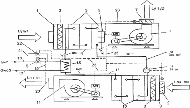
The drawing is a schematic diagram of the proposed installation of the exhaust air heat recovery L y in the drafting unit 1, consisting of a filter 2, teploizvlekayuschego heat exchanger 3 with the pallet 4 and the sensor 5 controls the condensate freezing, the exhaust fan 6 driven by a motor with magnetic actuator MP, the air valve 7 power and to feed the room to be served outside air L mon supply unit 8 consisting of an air valve 9 to the electric drive, the air filter 2, heat emitting coil 10, supply fan 11 driven by an electric motor with a magnetic actuator MF, and conduits 12 and 13 are connected teploizvlekayuschy 3 and the heat-10 heat exchangers, with a circulating pump 14 which is controlled by an automatic device 24 which controls the set temperature in the room to be ventilated, and on the pipe 13 is mounted heater antifreeze, which can operate in the defrosting mode, for example, a heat exchanger 15 antifreeze-hot water connected to the feed 16 and the return 17 conduits with a source of hot water supply (not shown), while feed pipe 16 is mounted an automatic valve 18 having a pulse link 19 with a sensor 20 controlling the supply of outside air temperature t bp, and the valve 18 is mounted bypass line 21 solenoid valve 22 having a connection 23 with an impulse control sensors 5 education frozen condensation on the surface of the heat exchanger plates 3 and the pulse connection 23 at the same time attached to the magnetic actuator 6 MP motor exhaust and supply fans 11 and air valves with electric actuators 7 and 9.
Installation of heat recovery from the exhaust air is as follows: highly efficient heat recovery cooled and dried exhaust air L the y with an initial enthalpy I y1 to the final enthalpy I v2, which is from the pump 14 is transmitted to the heating of the fresh outside air L mon with the temperature t Hx to a temperature t Mon, in the scheme of installing recycling is carried out when the motor exhaust air 7 and supply 11 fan and pump 14 controlled by an automatic device 24 that controls the desired temperature in the room to be ventilated, which line 12 feeds into the tube teploizvlekayuschego exchanger 3 antifreeze G af negative temperature t aF1 and, passing through the tubes of the heat exchanger 3, the hot antifreeze to positive temperature t af2 by extracting heat from the exhaust air determined by differential enthalpy (I y1 -I y2), wherein the heat exchanger plates 3 on condensate loss occurs, part of which is going to pallet 4 and removed in the sewers and partially freezes on cooling and drainage exhaust air L y, which is controlled by the sensor 5, and the excess of the critical level of freezing condensate will cause the command from the sensors 5 via impulse connection 23 to stop motor exhaust 6 and supply 11 fan, closing air valves 7 and 9, and the opening of the solenoid valve 22 in the bypass line 21 from supply conduit 16 proceeds hot water heat exchanger 15, that will improve temperature coolant to t af3 and heated antifreeze from the pump 14 via line 12 goes to the tubes of the heat exchanger 3, which determine rapid thawing of frozen condensate, which is a liquid is collected in the tray 4 and is removed in the sewers, and the elimination of frozen condensation on the surface of the heat exchanger plates 3 perceived sensors 5, which are pulse communication 23 transmits a command to start the motor exhaust air 7 and supply 11 fan, open air valves 7 and 9, the closing of the solenoid valve 22 in the bypass line 21, and if utilizable in the heat exchanger 3 the heat of the exhaust air L y is not enough to heat the fresh outside air L mon to the desired temperature t bp, the sensor 20 via the pulse link 19 a command to open automatic valve fine adjustment of the flow pipe 18 to 16, delivery of hot water G w r to the heat exchanger 15 to the reheating antifreeze G af3 to the desired temperature, as chilled water of w G about. reverse conduit 17 is supplied to the center of the water heating (not shown), to protect the heat exchangers 3 and 10 serve as a dust filter 2.
CLAIM
Installation of heat recovery from exhaust air containing teploizvlekayuschy heat exchanger with condensate tray in the drawing unit and the heat-exchanger in the supply unit, the heat exchangers are connected to pipelines that of the pump circulates antifreeze in units installed air valve, fan driven by electric motors, going on and off magnetic actuator, and filters for the protection of heat exchangers from dust, characterized in that mounted heater, wherein the heating in the heat-exchanger antifreeze is heated to a level specified by an automatic device that controls the temperature of heating the fresh outdoor air to the heat-exchanger, a and installed sensors control of condensate freezing, which have a pulse communication with magnetic motor starter fan exhaust and fresh air, but also the inclusion of antifreeze heater in defrost mode to eliminate the freezing of condensate falling from the cooled exhaust air on the walls teploizvlekayuschego heat exchanger, for example, a solenoid valve in the bypass pipe of hot water at the inlet of the heat exchanger antifreeze - water, set an automatic device to control the set temperature and the room to be ventilated controls the operation of the circulating pump.
print version
Publication date 07.12.2006gg
![]()

Comments
Commenting, keep in mind that the content and the tone of your messages can hurt the feelings of real people, show respect and tolerance to his interlocutors, even if you do not share their opinion, your behavior in terms of freedom of speech and anonymity offered by the Internet, is changing not only virtual, but real world. All comments are hidden from the index, spam control.