
| Start of section
Production, amateur Radio amateurs Aircraft model, rocket-model Useful, entertaining |
Stealth Master
Electronics Physics Technologies Inventions |
Secrets of the cosmos
Secrets of the Earth Secrets of the Ocean Tricks Map of section |
  |
| Use of the site materials is allowed subject to the link (for websites - hyperlinks) | |||
Navigation: => |
Home / Patent catalog / Catalog section / Back / |
|
INVENTION
Patent of the Russian Federation RU2201561
![]()
HEAT GENERATOR OF THE CAVITATION TYPE
The inventor's name: Lev Nikolaevich Britvin
The name of the patent holder: Britvin Lev Nikolaevich
Address for correspondence: 111673, Moscow, ul. Novokosinskaya, 13, building 1, ap. 76, L.N. Britvin
Date of commencement of the patent: 1999.05.19
The invention relates to heat power engineering. The cavity-type heat generator based on the use of a vortex nozzle driven from a pump-driver can be used as a mixer, homogenizer, dispersant in technological processes. To increase the efficiency at the outlet of the vortex nozzle nozzle, there is located at least one resonator in the form of an axisymmetric chamber, and in order to obtain an additional effect from the end of the vortex chamber, a second axisymmetric resonator, communicating with the cavity of the nozzle with a central hole, is opposed to its nozzle. At the same time, at least one resonator is made with an adjustable frequency, and to increase the total heat dissipation in oppositely located end walls of the resonators, electrodes are installed along their axis, which are communicated with the source of electric current. At the same time, to optimize the heat dissipation process, the ratio of current powers supplied to the driver pump and electrodes is adjustable.
DESCRIPTION OF THE INVENTION
The invention relates primarily to heat generators of cavitation type, and can be used in cavitation mixers, homogenizers, dispersants and the like. Devices.
Similar cavitation technological devices are known, containing a cavitation generator whose input is connected to a source of liquid under pressure (Fedotkin IM, Nemchin AF The use of cavitation in technological processes., Kiev: Visha school, 1984, p.12-13, 32 ) . These technical solutions are aimed at increasing the intensity of cavitation processes, but does not solve this problem definitively and requires complex technical solutions that do not exclude the wear of an element of a cavitation generator.
The closest in terms of physical and technical essence is the heat generation method using a cavitation whirlpool nozzle with an axial outlet nozzle (RF patent 2061195, 6 F 24 J 3/00) , according to which oscillations are generated by means of a system connected to the cavitator at a sufficiently strictly set flow rate Pressure to intensify the process of excessive heat generation.
The objective of this proposal is to simplify the design of the heat generator, increase its life in the conditions of the action of cavitation and a wide range of adjusting the flow of liquid through the cavitational heat generator, which is necessary to regulate the output heat output of the heat generator in the process of its operation.
This task is solved in a heat generator communicated with a drive pump whose output is connected to the inlet channel of a vortex nozzle provided with an axial outlet nozzle in that at the outlet of the vortex nozzle nozzle there is located at least one resonator of self-oscillations in the form of an axisymmetric chamber, And in that the outlet nozzle of the nozzle is located around the outlet of the first resonator opposite to which the second resonator is located and the circular cavity between them is hydraulically communicated with the peripherally located circular chamber communicated with the output channel of the heat generator. At the same time, at least one resonator made in the form of a blind or flowing chamber is configured to regulate its volume to adjust the heat generator to the maximum energy release mode.
In addition, along the axis of the heat generator in oppositely located ends of the resonators, protuberances with a smooth transition of their bases to the end walls of the resonators in which the electrodes connected with the electric voltage source are installed can be made located on the common axis of the resonators.
An additional effect on heat generation is achieved due to the combined supply of energy to the heat generator, namely by bringing electricity to the installed ends of the resonators in their central protuberances to the electrodes, while the ratio of the energies supplied through these two channels can be made adjustable to obtain the maximum efficiency of the heat generator .
 |
 |
In Fig. 1-3 give examples of the realization of heat generators of cavitation type, explaining the technical essence of this proposal.
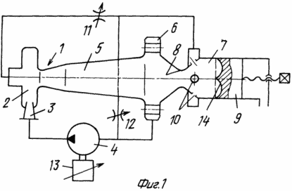
The cavity-type heat generator consists of a vortex nozzle 1 provided with a swirl chamber 2 of a flow, the inlet channel 3 of which is communicated with the output of the driver-impeller 4. The nozzle 1 is provided with an axial outlet nozzle 5 at the outlet of which the brake chamber of the flow 6 is communicated with the input of the driver pump 4. At the outlet of the nozzle 5, there is located a resonator 7 in the form of an axisymmetric chamber with an axially located inlet 8 which diffusely passes into the proper chamber of the resonator 7, made in this embodiment with an adjustable volume by means of an adjusting-movable piston 9. The chamber of the resonator 7 is provided peripherally Located outlet channels 10 and adjustable chokes 11 and 12, one of which may be missing to simplify the design. Chokes 11 and / or 12 serve to change the flow through the resonator and regulate the operating mode of the heat generator.
The pump 4 is equipped with a speed-controlled motor 13. The efficiency of the heat generator is increased by generating a pressure from the resonator 7 at a frequency determined by the position of the piston 9.
The pressure waves emitted by the resonator propagate throughout the core of the stream in the nozzle 5 and the chamber of the resonator 7, providing an increase in both the frequency of formation and collapse of the cavitation caverns in the volume of the flowing liquid, and the intensity of these processes.
When the pump 4 is changed by the drive 13, the resonator 7 can always be set to the maximum possible mode for a given heat dissipation rate.
The increase in the life of the heat generator is achieved by the fact that due to the vortex motion of the liquid, the formation and collapse of the cavitation caverns is carried out in the axial flow core, therefore the walls of both the vortex nozzle and the resonator are in the zone of increased pressure and are therefore protected from the destructive effect of pressure in collapsing caverns occurring on Distance from the walls.
The end wall of the resonator is thus protected from destruction by virtue of its execution smoothly transferring to the peripheral wall of the cavity chamber, but also due to the presence of a central axial projection 14 guiding the flowing stream to the axis of the resonator and further towards this flow along the axis of the resonator.
The possibility of controlling the pump 4 supply by the motor 13, the circulation costs by means of the chokes 11 and 12 and the natural frequency of the resonator by the piston 9 provides wide possibilities for adjusting the cavitation heat generator to the optimum operating mode and thereby allows obtaining the maximum ratio of the heat generated to the energy supplied to the engine 13, Regulation of the heat output of the heat generator, which significantly expands the operational capabilities of the heat generator.
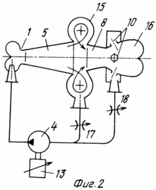
In Fig. 2 shows an example of a heat generator where two resonators are arranged in series at the outlet of the nozzle 5 of the vortex nozzle 1, one of which is made in the form of an exit from the nozzle 5 of the torus-like axisymmetric chamber 15 hydraulically communicated with the outlet of the nozzle 5 in its smaller diameter and the other in the form Located opposite the nozzle 5 of an axisymmetric chamber 16 of a drop-shaped shape with an axially disposed inlet 8 and outlets 10.
The hydraulic chambers 15 and 16 are connected to the inlet of the pump 4 via the adjustable chokes 17 and 18, allowing to change the ratio of the flow through the resonators 15 and 16. With the throttle 18 closed, the resonator 16 operates as a non-current resonator, while the speed of the torus-like vortex in the resonator 15 increases . With the throttle 17 closed and the throttle 18 open, the heat generator's working process is significantly different from the first case.
Thus, by regulating the chokes 17 and 18, a mode can be selected that ensures maximum heat release at a given pump feed 4. To minimize hydraulic losses, the outlet tubes of the resonators are arranged to meet the incoming flow, i. Tangentially to the chambers of the heat generator.
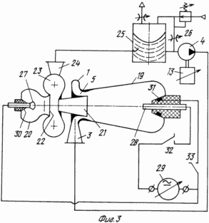
In Fig. 3 shows an embodiment of a heat generator with two resonators 19 and 20 arranged oppositely to each other. Here, the nozzle 5 of the vortex nozzle 1 is disposed around the outlet opening 21 of the resonator 19 opposite to which another resonator 20 is located with an inlet 22 coaxial with the opening 21. The cavity between the apertures 20 And 21 is hydraulically communicated with a peripherally located circular chamber 23 communicating with the output channel 24 of the heat source. The camera 23 in the embodiment may be configured as a torus-shaped resonator shown in FIG. 2, and the outlet opening 21 of the resonator 19 is like a confluent nozzle guiding the outflow into the center of the inlet 22 of the resonator 20.
When liquid is supplied to the inlet channel 3 of the vortex nozzle 1, a swirling flow of liquid leaves the nozzle 5 into the resonator 19, where its end wall rotates to the axis and is ejected through the nozzle opening 21 into the cavity of the resonator 20 along its axis and then along the periphery of the hole 22 Into the torus chamber 23 and tangentially located to the chamber 23, the branch pipe 24 exits from the heat generator, for example, to a separation tank 25 with a free liquid level and a stabilized pressure, and then again flows from the tank 25 to the input of the drive pump 4. With this movement of the liquid With an open valve 26 - a gas-liquid mixture) along the axis of the heat generator a vortex band is formed, saturated with cavitation cavities, which, due to the interaction of counter vortex flows and under the action of vibrations generated by the resonators, continuously form and collapse with a high frequency, determined in many respects by resonators 19 and 20 , Which significantly intensifies the cavitation processes and heat release in the liquid.
Since there is intense electrification of the flow along the axis of the vortex bundle due to mutual friction of the vapor and gas particles emitted from the liquid, this vortex bundle has a slight electrical resistance, which makes it possible to increase the heat release into the circulating fluid through the heat source, additionally by passing an electric current through the vortex bundle , Located between the end walls of oppositely located resonators 19 and 20.
Based on this, the cavitation heat generator shown in FIG. 3, is supplemented with electrodes 27 and 28 installed in the end walls of the opposing resonators and communicated with the source of the electrical voltage 29.
In order to reduce wear and to allow the cavitation flow to flow onto the electrodes towards the outlet chamber 23 and the branch pipe 24, the end walls are smoothly turned into central protrusions 30 and 31 facing each other in which electrodes 27 and 28 are mounted.
The voltage source 29 is connected to the electrodes, for example, by knife switches 32, 33 after the impulse pump 4 is turned on.
When the source 29 is regulated with a given feed of the drive pump, changing the current through the axial vortex bundle ensures maximum heat dissipation from the heat generator in relation to the total cost of energy supplied to the heat generator.
CLAIM
1. A cavity-type heat generator coupled to a drive pump whose output is connected to an inlet channel of a vortex nozzle provided with an axial outlet nozzle, characterized in that at the outlet of the nozzle there is arranged at least one resonator of self-oscillations in the form of an axisymmetric chamber.
2. The heat generator according to claim 1, characterized in that the outlet nozzle of the vortex nozzle is located around the outlet of the first resonator opposite to which the second resonator is located and the cavity between them is hydraulically communicated with a peripherally located circular chamber communicated with the output channel of the heat generator.
3. Heat generator according to. 1 and 2, characterized in that at least one resonator is provided with a variable volume.
4. The heat generator according to claim 2, characterized in that along the axis of the heat generator in oppositely arranged ends of the resonators are arranged projections on the common axis of the resonators with a smooth transition of their base to the end walls of the resonators in which the electrodes are connected to the source of electrical voltage.
print version
Date of publication 08.12.2006гг
![]()

Comments
When commenting on, remember that the content and tone of your message can hurt the feelings of real people, show respect and tolerance to your interlocutors even if you do not share their opinion, your behavior in the conditions of freedom of expression and anonymity provided by the Internet, changes Not only virtual, but also the real world. All comments are hidden from the index, spam is controlled.