
| Start of section
Production, amateur Radio amateurs Aircraft model, rocket-model Useful, entertaining |
Stealth Master
Electronics Physics Technologies Inventions |
Secrets of the cosmos
Secrets of the Earth Secrets of the Ocean Tricks Map of section |
  |
| Use of the site materials is allowed subject to the link (for websites - hyperlinks) | |||
Navigation: => |
Home / Patent catalog / Catalog section / Back / |
|
INVENTION
Patent of the Russian Federation RU2232357
![]()
HEAT GENERATOR FOR LIQUID HEATING (OPTIONS)
The name of the inventor: Rukavishnikov VA (RU); Tarchevsky E.P. (RU); Alexandrov M.P.
The name of the patent holder: Limited Liability Company Energosistemy (RU)
Address for correspondence: 121609, Moscow, Autumn Blvd, 11, (609 post office), "Patent Law Firm VIS", Pat. ND Koltsova
Date of commencement of the patent: 2002.12.06
The invention relates to the field of heat power engineering and can be used for heating and hot water supply, and can be used for heating viscous liquids during their transfer through pipelines. The heat generator includes, in the housing, at least one means for accelerating the movement of the fluid and at least one means for inhibiting the movement of the fluid, in the form of impeller wheels. One paddle wheel is rotatably mounted under the action of the drive coaxially with the other, mounted fixedly to form a gap between the blades of the impellers. In this case, according to a first embodiment, a partition is provided in the grooves between the blades of the stationary impeller, with the possibility of moving it along the blade's height. According to a second embodiment, the hub of the rotating impeller is configured such that the distance between its end and the end of the impeller is 1/4 of the blade's height. The technical result consists in increasing the efficiency, stability of the liquid heating process, and increasing the efficiency and power factor of the drive.
DESCRIPTION OF THE INVENTION
The invention relates to the field of heat power engineering and can be used for heating and hot water supply of buildings, structures, vehicles, in particular when eliminating emergencies caused by failures in the operation of central heating and hot water supply devices, the invention and can be used for heating viscous liquids under Their pumping through pipelines and to ensure other household needs associated with the supply of hot liquids.
A device is known for converting mechanical energy into thermal energy by changing the physico-mechanical parameters of the working medium, for example, pressure and volume (see USSR copyright certificate No. 458591, F 25 B 29/00, 1972), which includes a housing in the form of A spherical vessel filled with water, with a heat exchanger located in it, an electric motor pump that compresses the working medium inside the housing, supply and return pipelines equipped with shut-off valves, and a heat consumer.
The main drawback of the described analogue is the high working pressure in the case, reaching 100 MPa, which complicates the design and worsens the safety of operation.
The closest analogue (prototype) is the heat generator described in the patent of the Russian Federation No. 2045715, F 25 B 29/00, 1995 and including a body with a cylindrical part, a liquid flow accelerator comprising a fluid pump, and an injection inlet , Connected to a cyclone mounted on one of the ends of the cylindrical body part. The opposite end of the cylindrical part of the body has a bottom with an outlet communicating with the outlet of the housing. Inside the cylindrical part of the body there is a braking device with radially arranged ribs. In this case, the outlet branch pipe is connected via a bypass pipeline with a cyclone, and an additional brake device is installed in the area of their connection. When the pump is turned on, the liquid under pressure of 0.4-0.6 MPa is fed into the injection pipe, accelerated in it, spun in a spiral cyclone and braked on the walls of the cylindrical part of the body and the ribs of the brake device. As a result of changes in pressure and flow velocity, the liquid heats up and enters the heat exchangers.
The main drawback of the prototype is its unstable heat output (i.e., the amount of thermal energy received by the heated liquid per unit time), which is determined by the value of the useful mechanical power on the motor shaft. Deviations of heat output can reach 1.5-2 times both in the direction of its increase and in the direction of decreasing, while the actual value of the loading torque of the pump motor is self-aligned depending on the parameters of the high-velocity fluid flow in the heat generator channel. These parameters are reproduced as a result of the interaction of three unregulated elements of the construction: a flow channel, a pump and an electric motor. Under these conditions, even small deviations in performance lead to significant deviations in the magnitude of the loading torque and heat output. In the case of increased heat output, the motor operates with overload, which is inadmissible due to the possibility of overheating of its windings and failure. If the heat output decreases, the electric motor does not work and the heat generator does not produce the required amount of heat. As with an underload of the electric motor, and when it is overloaded by a loading torque different from the nominal one, the efficiency of the electric motor and the power utilization factor are reduced.
Thus, the object of the present invention is to provide a stable and predictable flow pattern of the fluid in the device. The technical result achieved in the implementation of the invention consists in increasing the efficiency, stability and controllability of the liquid heating process, and increasing the efficiency and power factor of the drive.
The design of the heat generator ensuring the achievement of the above-mentioned technical result in all cases to which the scope of the requested legal protection is applicable may be characterized by the following set of essential characteristics.
The heat generator includes, in the housing, at least one means for accelerating the movement of the fluid and at least one means for inhibiting the movement of the fluid in the form of impeller wheels and means for supplying liquid. The paddle wheels are coaxial with the formation of a gap between them. One paddle wheel is rotatably mounted under the action of the drive. Another impeller is fixed. On it in the groove between the blades is installed a partition with the possibility of its movement along the height of the blade.
Furthermore, in a particular embodiment of the invention, the blades on the first and / or second impeller can be formed on the end surface of the blade member at an angle to its radius.
Furthermore, in a particular embodiment of the invention, the first impeller and / or the second impeller can be mounted to adjust the clearance between their end faces.
Furthermore, in a particular embodiment of the invention, the device may include means for supplying fluid to the cavity between the impeller wheels.
In this case, the liquid supply means may be a screw member.
In a second embodiment, the heat generator includes, in the housing, at least one means for accelerating the movement of the fluid and at least one means for inhibiting the movement of the fluid, in the form of impeller wheels. The paddle wheels are coaxial with the formation of a gap between them. One paddle wheel is rotatably mounted under the action of the drive. Another impeller is fixed. The paddle wheel hub, which is rotatably mounted under the action of the drive, is designed so that the distance between its end and the end of the impeller is 1/4 of the height of its blade.
In fact, the impellers of a hydrodynamic coupling similar to those used to transfer torque between two shafts can be used in the device (Gavrilenko BA, Semichastnov IF Hydrodynamic transmission: Design, fabrication and operation .- M .: Mechanical Engineering, 1980). In a conventional hydrodynamic coupling, the coaxial and turbine wheels rotate with some slip relative to each other. In this regard, the working fluid is heated, but the amount of heat energy released is small in comparison with the value of the power transferred by the clutch. The immovable fixation of the turbine wheel (which in this case becomes reactive) makes it possible to convert all the mechanical energy of the electric motor into the thermal energy of the heated liquid.
The possibility of implementing the invention characterized by the above feature sets, and the possibility of implementing the assignments of the invention can be confirmed by describing the construction of a heat generator for heating a liquid made in accordance with the claimed invention.
Description of the construction is explained by graphic materials, which show the following:
 |
 |
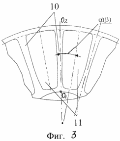 |
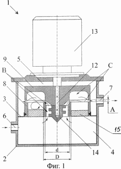
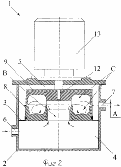
FIG. 1 is a schematic diagram of a heat generator (option 1). FIG. 2 is a schematic diagram of a heat generator (variant 2). 3 is a diagram of the formation of blades. |
In a first embodiment, the heat generator 1 for heating liquids comprises a housing 2, which is a thermally insulated tank with a liquid divided by a partition 3 into a drain 4 and a pressure compartment 5. In the drainage compartment 4, an inlet 6 is provided, and an outlet opening 7 is provided in the discharge compartment 7. The apertures are connected by means of a drain and discharge nozzles with at least one heat exchanger (not shown). In the housing 2, there are means for accelerating and inhibiting the movement of the fluid, made in the form of impeller wheels 8 and 9, which are two hydrodynamic transmission wheels with blades 10. The blades are the impeller 8 (the hydrodynamic transmission reaction wheel) and the impeller 9 (the pump wheel of hydrodynamic transmission) of the fin with grooves 11 between them. Between the blades of the impeller 9 is installed a partition 15. Moreover, this partition is installed with the possibility of moving it along the height of the groove. The longitudinal axes O 1 O 2 of the blades (ribs) are located at an angle ![]() =
= ![]() = 0 ° to the radius of the corresponding wheel, but may be located at an angle other than 0 °, including that they can be designed so that the blades 10 of the impeller 8 and the impeller 9 are directed towards each other. The impeller 9 is fixedly fixed in the housing 2, and the impeller 8 is mounted coaxially with it on the shaft 12 of the drive motor 13 with the possibility of rotating it. In the particular case, the impellers are arranged to adjust the gap A between the ends of the impeller wheels by moving the impeller 8 and / or 9 along the shaft 12. A fluid supply means 14 is provided on the shaft 12, which is in the form of a screw disposed in an inner aperture of the blade Of the element 8 to form a slit B for the passage of liquid from the drainage compartment 4 of the body into the cavity C between the impeller wheels 8 and 9. In this case, the diameter d of the circumference defining the inner ends of the paddle wheel grooves is less than the corresponding diameter D of the blade member, which facilitates the flow of liquid from the screw 14 through the slot B into the cavity C between the blade member and the impeller wheel.
= 0 ° to the radius of the corresponding wheel, but may be located at an angle other than 0 °, including that they can be designed so that the blades 10 of the impeller 8 and the impeller 9 are directed towards each other. The impeller 9 is fixedly fixed in the housing 2, and the impeller 8 is mounted coaxially with it on the shaft 12 of the drive motor 13 with the possibility of rotating it. In the particular case, the impellers are arranged to adjust the gap A between the ends of the impeller wheels by moving the impeller 8 and / or 9 along the shaft 12. A fluid supply means 14 is provided on the shaft 12, which is in the form of a screw disposed in an inner aperture of the blade Of the element 8 to form a slit B for the passage of liquid from the drainage compartment 4 of the body into the cavity C between the impeller wheels 8 and 9. In this case, the diameter d of the circumference defining the inner ends of the paddle wheel grooves is less than the corresponding diameter D of the blade member, which facilitates the flow of liquid from the screw 14 through the slot B into the cavity C between the blade member and the impeller wheel.
In a second embodiment, the heat generator 1 for heating liquids comprises a housing 2, which is a thermally insulated tank with a liquid divided by a partition 3 into a drain 4 and a pressure compartment 5. In the drainage compartment 4, an inlet 6 is provided, and an outlet opening 7 is provided in the discharge compartment 7. The apertures are connected by means of a drain and discharge nozzles with at least one heat exchanger (not shown). In the housing 2, there are means for accelerating and inhibiting the movement of the fluid, made in the form of impeller wheels 8 and 9, which are two hydrodynamic transmission wheels with blades 10. The blades are the impeller 8 (the hydrodynamic transmission reaction wheel) and the impeller 9 (the impeller of the hydrodynamic transmission) of the fin 11 with grooves therebetween. The longitudinal axes O 1 O 2 of the blades (ribs) 10 are arranged at an angle ![]() =
= ![]() = 0 ° to the radius of the corresponding wheel, but may be located at an angle other than 0 °, including that they can be designed so that the blades 10 of the impeller and the blade member face each other. The vane member 9 is fixedly fixed to the housing 2, and the impeller 8 is mounted coaxially to it on the shaft 12 of the driving motor 13 with the possibility of rotating it. In a particular embodiment, the impellers are arranged to adjust the gap A between the ends of the impeller wheels by moving the impeller along the shaft 12. The distance between the end surface of the hub of the impeller 8 and its end surface is 1/4 of the height of the blades of the wheel 8.
= 0 ° to the radius of the corresponding wheel, but may be located at an angle other than 0 °, including that they can be designed so that the blades 10 of the impeller and the blade member face each other. The vane member 9 is fixedly fixed to the housing 2, and the impeller 8 is mounted coaxially to it on the shaft 12 of the driving motor 13 with the possibility of rotating it. In a particular embodiment, the impellers are arranged to adjust the gap A between the ends of the impeller wheels by moving the impeller along the shaft 12. The distance between the end surface of the hub of the impeller 8 and its end surface is 1/4 of the height of the blades of the wheel 8.
DEVICE WORKS AS FOLLOWING
When the electric motor 13 is turned on, the liquid from the heat exchangers enters the drainage compartment 4 of the housing through the opening 6. In the first embodiment, from the compartment 4, the liquid is supplied by the screw 14 into the grooves of the impeller and accelerated by centrifugal forces from its center to the periphery where the flow is wound And, falling into the grooves of the blade element, is braked, moving to its center, and then again falls into the grooves of the impeller wheel. As a result, the liquid is heated and through the gap A under pressure enters the pressure chamber 5 of the housing and then through the hole 7 and the discharge connection to the heat exchangers.
The flow rate of the liquid through the flow channel of the heat generator and the pressure difference between the pressure and drain sections of the housing depend on the geometric dimensions of the screw 14. When the heat generator is in operation, the useful mechanical energy expended in rotating the impeller 8 almost completely goes into the heat energy of the heated liquid. Therefore, the heating capacity of the device can be determined by the product of the loading torque of the impeller wheel at the rotational speed of the shaft. In this case, the magnitude of the loading torque is stable, because Depends mainly on the active diameter of the impellers and can be calculated from known formulas for hydrodynamic gears. The actual value of the loading torque can be adjusted by moving the partition between the blades along the blades. This makes it possible to use the same heat generator with drive motors of different capacities.
In addition, within a small range, the actual value of the loading torque can be adjusted by changing the size of the gap A in order to approximate the nominal torque of the motor. In the second embodiment, there is no auger, however, the shortened hub impeller hub allows water to be supplied to the space between the impeller and the blade member. Since there is no special means for supplying liquid, the design of the heat generator is simplified.
Thus, the proposed variants of the heat generator design allow reproducing the loading of the motor with a nominal torque, which ensures a stable heat output corresponding to the rated power of the electric motor, with the maximum efficiency and ensures its versatility.
The above-described embodiments of a heat generator for heating a liquid made in accordance with the claimed invention prove the possibility of realizing the purpose of the invention and achieving the above technical result, but it does not exhaust all the possibilities for implementing the invention characterized by the combination of features given in the claims.
CLAIM
1. A heat generator comprising, in the housing, at least one means for accelerating the movement of the fluid and at least one means for inhibiting the movement of the fluid, in the form of impeller wheels arranged coaxially with a gap between their end surfaces c And a means for supplying fluid to the cavity between the impeller wheels, wherein the first impeller is rotatably mounted under the action of the drive, characterized in that the second impeller is fixedly mounted in the housing, and in the grooves between its blades, The height of the blades.
2. The heat generator according to claim 1, characterized in that the blades on the first and / or second impeller are at an angle to its radius.
3. The heat generator according to claim 1 or 2, characterized in that the first impeller and / or the second impeller are arranged to adjust the clearance between their end faces.
4. The heat generator according to any one of claims 1 to 3, characterized in that the liquid supply means is a screw member.
5. A heat generator comprising, in the housing, at least one means for accelerating the movement of the fluid and at least one means for inhibiting the movement of the fluid, in the form of impeller wheels arranged coaxially with a gap between their end surfaces c With the first impeller rotatably mounted under the action of the drive, characterized in that the second impeller is fixedly mounted in the housing and its hub is configured such that the distance from its end surface to the end surface of said impeller is 1/4 of the height Blades.
6. Heat generator according to claim 5, characterized in that the blades on the first and / or second impeller are at an angle to its radius.
7. A heat generator according to claim 5 or 6, characterized in that the first impeller and / or the second impeller are arranged to adjust the clearance between their end faces.
print version
Date of publication 25.01.2007gg
![]()

Comments
Commenting on, remember that the content and tone of your message can hurt the feelings of real people, show respect and tolerance to your interlocutors even if you do not share their opinion, your behavior in the conditions of freedom of expression and anonymity provided by the Internet, changes Not only virtual, but also the real world. All comments are hidden from the index, spam is controlled.