| Start of section
Production, amateur Radio amateurs Aircraft model, rocket-model Useful, entertaining |
Stealth Master
Electronics Physics Technologies Inventions |
Secrets of the cosmos
Secrets of the Earth Secrets of the Ocean Tricks Map of section |
|
| Use of the site materials is allowed subject to the link (for websites - hyperlinks) | |||
Navigation: => |
Home / Patent catalog / Catalog section / Back / |
|
INVENTION
Patent of the Russian Federation RU2021563
![]()
G. STEPANOVA, THE STROKE ELECTRIC HEATER
The name of the inventor: Stepanov Guri Nikolayevich
The name of the patent owner: Stepanov Guri Nikolayevich
Address for correspondence:
Date of commencement of the patent: 1991.03.25
Use: heating of premises by heating water in an open and closed system of heat supply, providing hot water for domestic needs and water treatment in boiler rooms by coagulation of substances dissolved in water. SUMMARY OF THE INVENTION: the electric outlet of the electric heater is connected to the middle of the inner electrode and is led outward through the wall of the tubular electrode, at the ends of the inner electrode arms, one insulating cap with polyhedral surfaces on the outside is threaded onto each arm of the electrode, with a radial magnetic circuit wrench driven by a portable electromagnetic key , The power supply of the electric heater contains batteries with alternating and direct currents.
DESCRIPTION OF THE INVENTION
The invention relates to heating of premises by heating water in an open and closed system of heat supply, provision of hot water for domestic needs and water treatment in boiler rooms by coagulation of substances dissolved in water.
For example, a single-phase flow-through electric heater is known in which water is heated when an alternating electric current flows through the water column between the outer tubular electrode (body) and the internal electrode coaxially inserted into it from its end (housing).
The disadvantage of the electric heater is that it serves only for heating the water and in it water can not be processed from scaling, is complex in structure, has manually operated moving parts, large dimensions and extra depressurization units.
The aim of the invention is to increase the reliability of the electric heater with the exception of manually operated moving parts, reduce the specific weight, overall dimensions and increase the efficiency of electric heating and water treatment.
 | |
 |
 |
 | |
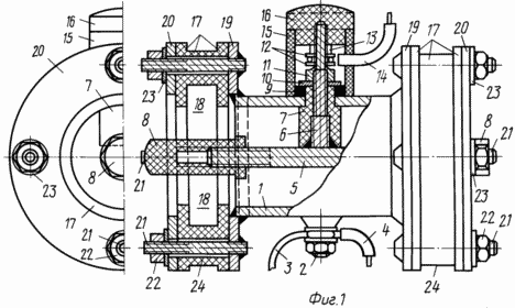
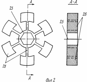
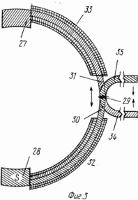
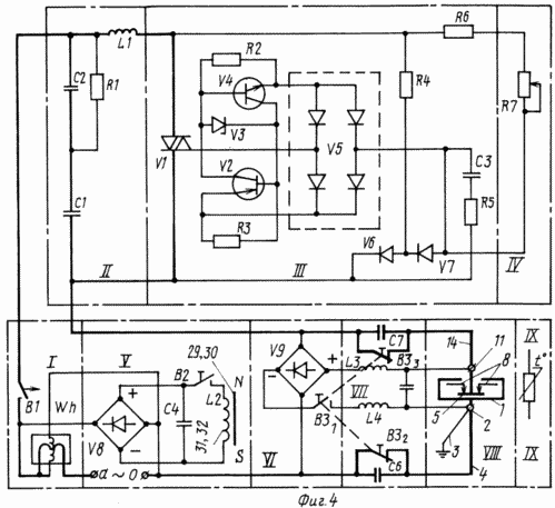
In Fig. 1 shows an electric water heater; FIGS. 2 and 3 show the construction of a wrench and an electromagnetic key; 4 is an electrical diagram of the power supply unit.
Referring to Fig. 1 and 2, the electric heater consists of an outer tubular electrode 1 with a grounding bolt 2 connected by a wire rod 3 to a grounding electrode (not shown in FIG. 1), an AC network zero wire 4, and a negative (-) rectifier Y9 of the power supply unit (FIG. 4) , Coaxially located inner two-arm electrode 5 with terminal 6 from its center through insulating sleeve 7, two insulating caps 8 with polyhedral surfaces externally mounted on the threads at the ends of each of the arms of inner electrode 5, insulating 9 and sealing washers 10, extension 11 for connecting Washers 12 and the nut 13 of the AC mains lead 14 through the thyristor voltage regulator VI (Fig. 4) and the positive terminal from the rectifier Y9, the insulating tube 15 and the insulating clip 16 to prevent contact with the extension 11, the gasket 17 to form an insulation gap between An internal electrode 5 and a heating network pipeline (not shown in FIG. 1), chambers 18 formed on the inside of the gaskets 17 disposed therein and fitted to the insulating caps 8 of the two screwdrivers 25 (FIG. 2) with the radially disposed magnetic circuits 26 welded To the ends of the outer tubular electrode 1 of the two flanges 19 and the two counter flanges 20 welded during installation to the heating system piping, which are subsequently joined together with the gaskets 17 by the studs 21, nuts 22 and washers 23 formed on the outer surfaces of the gaskets 17 between the flanges 19 and 20 of the grooves 24 For positioning the magnetic heads 27 and 28 of the portable electromagnetic key in them (FIG. 3).
In accordance with FIG. 3, the portable electromagnetic key consists of magnetic heads 27 and 28 at the ends of two coaxially arranged magnetic axes 30 and 31 on axis 29, windings 32 and 33 wound thereon, subsequently connected in parallel or series to rectifier U8 with capacitance C4 of unit (Fig. 4), and handles 34 and 35, one of which has a switch B2 (not shown in Fig. 3).
Referring to FIG. 4, the power supply unit has a Wh power meter and a starter B1, a radio interference filter (node II) with an inductor LI and capacitances C1 and C2, a thyristor voltage regulator (see node III) with a potentiometer R7 (node IV) , A rectifier Y8 with a switch B2, a capacitance C4 and an inductance L2 (node V) for supplying the windings 32 and 33 (Fig. 3) of the portable electromagnetic key, rectifier Y9 (node VI) with a switch B3 1 , switches B3 2 and B3 3 , Capacitances C6 and C7 when disconnecting from the rectifier U9 electric heater circuit breaker B3 1 , filters (node VII) from an electric current with a frequency of 50 Hz in the rectifier circuit V9 with inductances L3, L4 and capacity C5, and with capacitances C6 and C7 in the phase and Zero conductors of the alternating current network to eliminate the direct current in the alternating current circuit with a frequency of 50 Hz, the electric heater (node VIII) and Fig. 1), the thermostat (node IX) for automatically switching off and switching on the power supply unit B1, depending on the set maximum or minimum Water temperatures in the heating system or the environment in the room.
The electric water heater (Fig. 1) after installation in the heating system filled with water through the expansion tank (not shown in Figs. 1-4), the starter B1 is connected to the power unit and at a fixed time, by the initial and weekly power meter Indication Wh The installed capacity of Py at a given specific electrical conductivity (mineralization) of water; If the PN at this and the nominal voltage in the AC power supply at the external 1 and internal electrodes of the electric heater is higher than the permissible operating conditions, then with the help of the portable electromagnetic key (FIG. 3) and the wrench 25 (FIG. 2), the insulating caps 8 Both shoulders of the inner electrode 5 or vice versa are twisted at a value of PN below the calculated one. In the event that it is impossible to reduce the value of Py in this manner to the permissible level, then the direct current from the rectifier V9 is supplied to the electric heater by switching on the circuit breaker B3 1 to reduce the specific conductivity of the water due to the partial coagulation of the salts dissolved in it. In the future, such operations are carried out with a complete replacement of water in the heating system or its refilling in large doses. To change Py by electromagnetic key, its windings 32 and 33 (Figure 3) are connected through switch B2 to the rectifier U8 with a capacitance C2 (Figure 4), the magnetic heads 27 and 28 are alternately located in the grooves 24 (Fig.1), by pressing the switch B2, direct current is supplied to the windings 32 and 33, and by means of handles 34 and 35, the electromagnetic key is rotated clockwise, for example, with decreasing Py; then by electromagnetic coupling between the magnetic flux cores 30 and 31 of the electromagnetic wrench and 26 of the wrench 25 (FIG. 2) the caps 8 (Fig. 1) are twisted, reducing the active part of the inner electrode 5, and for winding the next beam of the magnetic wrench 26 of the wrench 25 by the switch B2, the windings 32 and 33 are cut off from the rectifier V8 and the opposite movement is performed - the process is repeated like the usual wrench Key. During operation, the temperature of the water in the heating system or indoor air is smoothly controlled by changing the power consumption of the electric heater by increasing or decreasing the mains voltage by the thyristor regulator to account for the change in the resistance value on the potentiometer R7 (Fig. 4) or the optimum air temperature in the room is maintained at a constant power consumption for The account of automatic switching-off or inclusion of an electric heater by the actuator B1 from action of a temperature regulator depending on sizes of the set maximum and minimum values of temperatures of water in heating system or air in a premise.
CLAIM
A flow-through electric heater comprising a tubular electrode with a grounding bolt and two flanges, counter flanges connected through insulating spacers with flanges with studs with nuts and washers, an internal electrode with an electrical terminal and a power supply connected to the electrical terminal and a grounding bolt, characterized in that , In order to improve reliability, the electrical connection is connected to the middle of the inner electrode and is led out through the side wall of the tubular electrode.
2. An electric heater according to claim 1, characterized in that, in order to isolate the electrical output of the inner electrode from the tubular and electrical protection, it comprises an insulating sleeve, an insulating and sealing washer, an extension, clamping washers, a nut, an insulating tube and an insulating clip, The electrical outlet of the inner electrode is threaded and an insulating sleeve is placed on it with an outlet through the sidewall of the tubular electrode pressed against the inner wall of the tubular electrode through an insulating and sealing washer which is screwed onto the thread with an extension with a nut and clamping washers to which the insulating clip is screwed, Fixing the insulating tube on the outer surface of the tubular electrode.
3. The electric heater according to claim 1, characterized in that, in order to control the installed power, depending on the conductivity of the water, it contains two insulating caps with polyhedral surfaces from the outside, and the ends of the inner electrode are threaded to install insulating caps.
4. An electric water heater according to claim 3, characterized in that, in order to avoid depressurization when changing the length of the active part of the inner electrode by twisting or unscrewing the insulating caps, it comprises two wrench with ray-like magnetic circuits and a portable electromagnetic key, wherein the wrench is located in the chambers formed with The inner side of the insulating pads, between the flanges and counter flanges.
5. An electric water heater according to claim 4, characterized in that, in order to provide control of the electromagnetic key, the number of beams of the magnetic circuits and internal faces is equal to the number of faces on the surface of the insulating caps.
6. An electric water heater according to claim 4, characterized in that, in order to provide control, the wrench comprises two magnetic heads, two bracketed magnetic circuits with windings, two handles, an axis and a switch, the magnetic heads being located at the ends of the magnetic circuits connected by an axis Handles, one of which has a switch.
7. The electric water heater according to claim 1, characterized in that, in order to increase the efficiency of heating and water treatment, the power unit comprises alternating and direct current power cells.
8. Electric water heater according to claims 1 and 7, characterized in that, in order to supply the water heater with alternating and direct current, adjust the power consumption of the water heater at a constant installed capacity, supply the windings of the portable electromagnetic key and maintain the temperature of water or air in the room in specified Limits, the power unit contains an electric meter, a starter, a radio interference filter, a thyristor voltage regulator with a potentiometer, a first rectifier with a switch for supplying an electromagnetic key, a second rectifier and a 50 Hz filter and a temperature controller, to the first rectifier connected to the AC The electromagnetic key is connected to the winding of the electricity meter, an electromagnetic key is connected to the second rectifier connected to the AC mains through a series-connected radio interference filter, the starter and the current winding of the meter; they are connected through a filter with a frequency of 50 Hz, the electrical terminal of the internal electrode and the grounding bolt, and the thyristor regulator The voltage with a potentiometer is connected in parallel to the filter against radio interference.
print version
Date of publication 25.01.2007gg


Comments
When commenting on, remember that the content and tone of your message can hurt the feelings of real people, show respect and tolerance to your interlocutors even if you do not share their opinion, your behavior in the conditions of freedom of expression and anonymity provided by the Internet, changes Not only virtual, but also the real world. All comments are hidden from the index, spam is controlled.