| section Home
Production, Amateur Radio amateur Model aircraft, rocket- Useful, entertaining |
Stealth master
Electronics Physics Technologies invention |
space Mystery
Earth Mysteries Secrets of the Ocean Stealth section Map |
|
| Use of material is permitted for reference (for websites - hyperlinks) | |||
Navigation: => |
Home / Products Patents / In the section of the catalog / back / |
|
INVENTION
Russian Federation Patent RU2243617
![]()
SOLID thermoelectric devices
Name of the inventor: Picone Vincenzo (IT)
The name of the patentee: PELTEK Srl (IT)
Address for correspondence: 103062, Moscow, ul.Pokrovka, 27, p 1AG Agency "INTELS".
Starting date of the patent: 2000.02.18
The invention relates to a thermoelectric energy conversion. The inventive solid state thermoelectric device comprises an array of metallic conductor and / or semiconductor thermoelectric elements of n-type and p-type, mounted on a printed circuit and forming a thermocouple is electrically connected in series. Structure comprising at least a pair of laminated elements, each formed of a supporting layer prepared from a polymeric material and at least a layer of conductive material layer joining material disposed between said two laminated elements of polymeric material to lasting for connecting them with each other. Printed circuit obtained from a layer of conductive material of the laminated elements and electrically connects in series the thermoelectric elements to form a thermocouple having the hot and cold sides, respectively, on only one side of the structure. The construction of the thermoelectric device has rolled into a spiral or circular configuration. EFFECT: increased efficiency.
DESCRIPTION OF THE INVENTION
The present invention generally relates to thermoelectric devices and more particularly to a thermoelectric device for use in solid state thermoelectric heat pump.
The thermoelectric effect is a phenomenon that takes place in the presence of temperature differences in the electrical circuit. An example of thermoelectric effect is the Peltier effect. Simply put, if an electric current is passed through a metal-metal or metal-semiconductor, depending on the direction of the electric current passage heat evolved or absorbed. Peltier effect is reversible, that is, if the direction of the electric current is reversed, the cold junction becomes hot, and the hot junction becomes cold. It has been found that the higher the temperature difference is achieved by using metal-semiconductor junctions than with metal-metal junctions. Peltier effect is the principle of solid-state thermoelectric pumps.
As used herein, "thermoelectric device" called solid state device, wherein for heating or cooling material used Peltier effect. "Thermoelectric elements" referred to a metallic conductor or a semiconductor wafer. The term "thermocouple" means a combination of two thermoelectric elements that are on one end thereof electrically connected in series through the electrode.
BACKGROUND OF THE INVENTION
Solid-state thermoelectric heat pumps produced on an industrial scale since 1960. Initially, thermoelectric heat pumps contain metal elements based conductor. Currently, modern semiconductor technology provides the possibility of solid-state thermoelectric heat pumps with thermoelectric elements formed of Bi 2 Te 3 alloy, PbTe, SiGe, BiSb n-type and p-type. The thermoelectric devices that are generally known in the prior art have a planar configuration of variable geometry. In this kind of thermoelectric devices thermocouple supported by a sandwich structure elements derived from a ceramic material based on Al 2 O 3, a copper laminate.
SUMMARY OF THE INVENTION
The present invention provides a thermoelectric device with a new arrangement of thermocouples formed of metallic conductor and / or semiconductor thermoelectric elements tapa n-and p-type. The present invention provides a receiving and heat pump comprising the thermoelectric device of the present invention.
In accordance with a first embodiment of the present invention, the solid state thermoelectric device includes at least a matrix of metallic conductor and / or semiconductor thermoelectric elements of n-type and p-type, mounted on a printed circuit, whereby said thermoelectric elements form thermocouples, electrically connected in series and characterized in that it has a structure formed of at least a pair of laminated elements, each formed of a supporting layer consisting of a polymeric material and at least a layer of conductive material,
layer joining material disposed between said two laminated elements of polymeric material with each other for firm connection, and that
Printed circuit obtained from a layer of conductive material of the laminated elements and electrically connects in series the thermoelectric elements to form a thermocouple having the hot and cold sides, respectively, on only one side of the structure, and in that
said structure of the thermoelectric device is folded into a spiral or circular configuration.
In accordance with a second embodiment of the present invention, the solid state thermoelectric device includes at least a matrix of metallic conductor and / or semiconductor thermoelectric elements of n-type and p-type, mounted on a printed circuit, whereby said thermoelectric elements form an electrically connected in series thermocouple and characterized in that it has a structure formed of
laminated element formed of a supporting layer formed of a polymeric material and a layer of conductive material on each surface thereof,
connecting the layer of material located between the end portions of the laminated elements for firm connection between them, and in that
Printed circuit obtained by at least one of the layers of conductive material of the laminated element and electrically connects in series the thermoelectric elements to form a thermocouple having the hot and cold sides, respectively, on only one side of the structure, and in that
said construct is folded in a spiral or circular configuration.
BRIEF DESCRIPTION OF THE DRAWINGS
The present invention will be described in more detail with reference to the accompanying drawings, where:
 |
 |
|
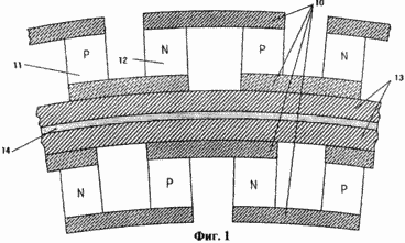
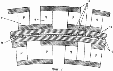
Figure 1 - a partial cross-sectional view of the thermoelectric device according to the first embodiment of the present invention. Figure 2 - a partial cross-sectional view of the thermoelectric device according to a second embodiment of the present invention. | |
 |
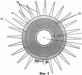 |
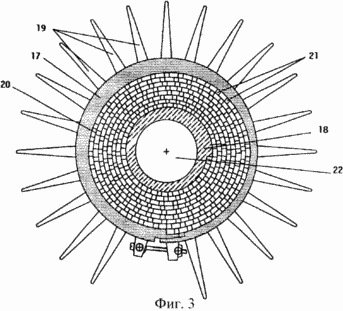
3 and 4 - a cross-section of the thermoelectric device according to the first or second embodiment of the present invention applied for a solid-state heat pump. | |
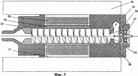 | |
5 - longitudinal section of the thermoelectric device according to the first or second embodiment of the present invention used to prepare the solid state heat pump. | |
 | |
6 - top view of the first pattern of the printed circuit used to form the thermocouples of the thermoelectric device according to the first or second embodiment of the present invention. | |
 | |
Figure 7 - top view of the second pattern of the printed circuit used to form the thermocouples of the thermoelectric device according to the first or second embodiment of the present invention. | |
 |
 |
|
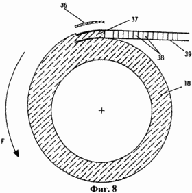
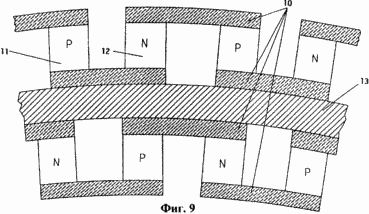
8 - a cross-section of the fastening means for connecting the thermoelectric device according to the first or second embodiment, the inner tube of the heat pump heat exchanger. 9 - a partial cross-sectional view of the thermoelectric device according to a third embodiment of the present invention. | |
 | |
10 - top view drawing of the printed circuit used to form the thermocouples of the thermoelectric device according to a third embodiment of the present invention. | |
 | |
11 - bottom plan view of the pattern of the printed circuit used to form the thermocouples of the thermoelectric device according to a third embodiment of the present invention. | |
 |
 |
|
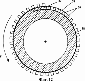
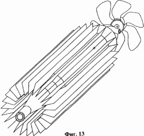
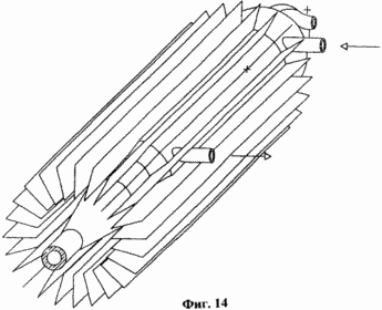
12 - cross section of the fastening means for connecting the thermoelectric device according to a third embodiment of the present invention, the inner tube of the heat exchanger solid state heat pump. 13 and 14 - heat pump isometric image provided with any one embodiment of the thermoelectric devices of the present invention. | |
 | |
DETAILED DESCRIPTION OF PREFERRED EMBODIMENTS
1 illustrates a first embodiment of a thermoelectric device according to the present invention. In accordance with a first embodiment of the thermoelectric device comprises a pair of laminated elements, each formed from a layer of polymeric material and a layer of metallic material, usually copper. The two laminated elements are mutually and directly joined together through their layers of polymeric material by introducing an adhesive between the polymer having high thermal conductivity such as epoxy resin containing silver filler or metal oxide. United thus rolling elements layered in a spiral or circular configuration to form the frame of the thermoelectric device used for the solid-state thermoelectric heat pump. Drawing of the printed circuit to which the thermoelectric elements are connected, get etched metal layer. Consequently, each turn of the spiral or circular wound core formed from a pair of laminated elements joined together by adhesive. Numeral 10 designates the cross section of metal wirings to which eutectic tin-based thermoelectric elements are soldered, respectively 11 and 12 of n-type and p-type. Numeral 13 designates the cross section of the layer of polymeric material and numeral 14 indicated a layer of glue which connects together the two laminated elements of the spiral or circular wound core to give it compactness and dimensional stability. The thickness of the metal wirings 10 will vary depending on the power and, therefore, the maximum value of the electric current flowing in the thermoelectric device according to the present invention. The thickness of the conductive paths, of course, should not be sufficient to prevent overheating of wiring due to the Joule effect. Preferably, the thickness of the conductor tracks is in the range 70-300 microns. The thickness of the layer of polymeric material 13 depends on the mechanical force used in winding and packing the core of the thermoelectric device. In practice the thickness of the conductive path to be selected to assure on one hand a good mechanical strength and on the other hand - the effective heat transfer. Preferably, the thickness of the conductive path was in the range of 50 to 150 microns. the adhesive layer 14 should condense and smooth contact surfaces of two laminated elements to prevent the formation of air bubbles and to align possible surface irregularities. The adhesive layer 14 and is intended to guarantee good heat transfer. For this purpose, a thermosetting resin to be used, for example, epoxy resin containing finely ground metallic filler. To limit the amount of coating material and to form a thin layer, the thickness of which is preferably not more than 10-15 microns, the resin is applied by a knife. The resin composition must be so that it is both completely cured during solder soldering the thermoelectric elements which is carried out at a temperature of 140 ° C in the case of the thermoelectric semiconductor elements and n-type of p-type.
2 illustrates a second embodiment of a thermoelectric device according to the present invention. In accordance with this embodiment, the thermoelectric device comprises a pair of laminated elements, each formed from a layer of polymeric material and two layers of metal, usually copper layers disposed on opposite surfaces of the two layers of polymeric material. The two laminated elements are mutually and directly joined together through their thinner layers of metal by soldering. Depending on whether the core forms a spiral or circular coils should be used eutectic alloy layer of Sn-In, which has a melting temperature of 118 ° C, eutectic alloy layer or Sn-Bi, which has a melting temperature of 135 ° C. Figure printed circuit supporting the thermoelectric elements are obtained on the thicker metal layer of each laminated elements. The two laminated elements are simultaneously brazed with semiconductors by soldering in the case of a coiled spiral core mold and subsequently coiled in the case of the circular shape of the core. In both cases, the final result is a wound core, intended to receive the solid state heat pump. Numeral 10 designates the cross section of metal wirings, which are soldered on the basis of eutectic tin soldered thermoelectric elements 11 and 12 of n-type and p-type respectively. Numeral 13 designates the cross section of the layer of polymeric material and numeral 15 indicated a thin metal layer. Numeral 16 designates the cross section of the layer of eutectic Sn-In alloy or Sn-Bi, which joins together the two laminated elements of the spiral or circular wound core to give it compactness and dimensional stability. The thickness of the metal wirings 10 will vary depending on the power and, therefore, the maximum value of the electric current flowing in the thermoelectric device according to the present invention. The thickness of the conductive paths, of course, should not be sufficient to prevent overheating of wiring due to the Joule effect. Preferably, the thickness of the conductor tracks is in the range 70-300 microns. The thickness of the layer of polymeric material 13 depends on the mechanical force used in winding and packing the core of the thermoelectric device. In practice the thickness of the conductive path to be selected to assure on one hand a good mechanical strength and on the other hand - the effective heat transfer. In the second embodiment, a thin metal layer 15 is not etched because its objective is to provide mechanical strength. Consequently, its thickness should preferably be in the range 35-100 microns. The thin metal layer 15 is designed to maintain the eutectic alloy used for the final soldering of the two laminated elements of the spiral or circular wound core. Preferably, the thickness of the thin metal layer 15 is from 15 to 30 microns. The layer of eutectic alloy 16 is deposited in advance, at least one of the two laminated elements, for example by screen printing or service through a mask to distribute the composition thixotropic dispersion of the eutectic tin alloy formed with an appropriate flux. The choice of a thermoelectric device made according to the first or second embodiment of the present invention depends upon the design specifications and the manufacturing costs.
3 and 4 illustrates a cross-sectional view of the thermoelectric device according to the first or second embodiment of the present invention. This thermoelectric device is used for solid state heat pump. The size of the heat pump may vary depending on the rated power. Reference numerals 17 and 18, said inner and outer tubes, respectively, the heat exchanger used in the solid state thermoelectric heat pump. Numeral 19 shown cooling fins external heat exchanger tube. The external heat exchanger tube 17 is arranged around the spiral or circular wound core 20 shown in Figures 3 and 4. The temperature of the cooling fins depends on the quantity of heat that should be dissipated, taking into account the fact that the temperature of the heat exchanger tubes must not exceed 50 55 ° C in order to ensure good operation of the heat pump. In an alternative embodiment, the heat exchanger tube 17 can be provided with smaller cooling fins and internally provided with a cavity through which coolant is circulated. The whole heat exchanger tube 17 can be made of aluminum and its thickness should be able to give some flexibility to the design in order to guarantee the seal surfaces in direct apposition. Furthermore, in the case of the spiral wound core illustrated in Figure 3, the outer contour of the heat exchanger tube 17 should take into account the eccentricity structure that forms coiled into a spiral core. As is apparent, in the thermoelectric device according to the first and second embodiments, the core has a structure formed of all the thermocouples supported layer of polymeric material laminated elements. The coils forming the wound core tightly packed and joined together by a thermally conductive adhesive in the case of the laminated elements illustrated in Figure 1, or by means of Sn-In or Sn-Bi eutectic alloy in the case of the laminated elements illustrated in Figure 2. The number of coils forming the wound core depends on the rated power of the thermoelectric heat pump. Experimental results show that optimal performance is obtained when the number of turns in the range of 1 to 15 without excessive manufacturing costs. Numeral 21 illustrates the location of two metallic conductor or semiconductor thermoelectric elements n-type and p-type soldered on soldering structure of the spiral or circular wound core. Heat exchanger tube 18 can be entirely made of copper, and in case the spiral wound core illustrated in Figure 3, it is contoured to provide, in the portion where the laminated elements is directly supported, a groove which compensates for the eccentricity caused by the design, forming a coiled core. If this is the case, it prevented the emergence of any field lack of contact interaction that occurs between the laminate elements and the metal surface of the inner tube 18 of the heat exchanger. Finally, reference numeral 22 contains an internal hollow portion of the internal heat exchanger tube 18 through which the flow of the working fluid.
5 illustrates a longitudinal section of the heat pump shown in Figure 3. Numeral 20 illustrates the location of the spiral or circular wound core inside the heat pump. The coils are closely packed and the external and internal tubes 17 and 18 respectively of the heat exchanger are mounted so as to prevent the formation of air bubbles between the surfaces that are in contact. The internal heat exchanger tube 18 is contoured to take into account the eccentricity of the resulting design spiral wound core. In contrast, the inner end portions of the heat exchanger tube 18 have a substantially circular cross section. Dimensions internal heat exchanger tube 18, of course, depend on the intended heat exchange. The heat pump is provided with two end caps 23 and 25 which close the heat pump assembly. The front cover 23 is made of a thermoinsulating polymeric material, such as polytetrafluoroethylene, polyvinylidene fluoride, polyamide-6,6, high density polyethylene, in order to thermally isolate the corresponding side of the heat pump and avoid the formation of condensate. The choice of material depends on the design specifications. The external heat exchanger tube 17 that surrounds and covers the wound core 20 is circular in cross-section in the case of a circular wound core, whereas its outer contours such as to take into account the eccentricity design formed coiled core when the spiral wound core. External heat exchanger tube 17 should have a thickness that ensures appropriate flexibility in its seal and freeze around the collapsed core. Numeral 19 shown cooling fins which are integral with the outer tube 17 of the heat exchanger. The total surface of the radiation fins depends on the nominal capacity and whether or not to apply the system of forced air cooling. In an alternative embodiment, the outer tube 17 of the heat exchanger can be used with smaller cooling fins and internally provided with a cavity through which coolant is circulated. Numeral 24 Set stator centrifugal pump circulation pump provided inside the rear cover 25 of the heat pump. The flow rate of the circulation pump depends on the overall extent of heat exchange circuit and the intended heat exchange rate. The example illustrated in Figure 5 relates to heating or cooling systems, wherein one heat pump is provided in the heat exchange circuit. However, there can be obtained and the modular heating and cooling system comprising two or more heat pumps connected in series, and a circulation pump for the heat pump provided outside. Numeral 26 indicated the impeller of the circulation pump. The impeller 27 is fixed on the shaft motor (not shown). A cooling fan for generating a forced air stream to be passed through the cooling fins 19 of the outer tube 17 of the heat exchanger, and can be mounted on the shaft 27. The rear cover 25 is made of a thermoinsulating polymeric material, such as polytetrafluoroethylene, polyvinylidene fluoride, polyamide-6,6, high density polyethylene, in order to thermally isolate the corresponding end part of the heat pump and avoid the formation of condensate. The choice of material depends on the design specifications. In the case of modular heating or cooling systems wherein two or more heat pumps connected in series, the two covers may be completely identical and symmetrical to one another. In this case, the circulation of working fluid through the heat pump will be guaranteed by an external circulation pump. Finally, the reference numeral 28, contains the metallic spiral inserted in the internal heat exchanger tube 18. The metal spiral 28 is designed to increase the residence time of the working fluid inside the heat pump and to generate a turbulent flow which enhances the heat transfer. The metal spiral 28 can be made of stainless steel and mounted with interference fit inside the internal heat exchanger tube 18 during the execution of the final assembly operation of the heat pump.
Figure 6 illustrates a first pattern of the printed circuit of the laminated elements of the thermoelectric pump according to the present invention in which the thermoelectric elements are supported. The length and width of the laminated element with the printed circuit and the lengths L1, L2 of the end portions of its rated power depends on the heat pump and, therefore, they are limited by design specifications. For a rated power less than 500 W may be provided a configuration in which one uses matrix of thermoelectric elements connected in series. For higher rated power wirings of the printed circuit should have a greater thickness. Numeral 29 contains the end portion of the laminated element, intended for fixing it to the inner tube 18 of the heat pump heat exchanger. Numeral 30 shown connecting terminals of the printed circuit, which is connected to an external power source. Numeral 31 contains the printed circuit on which are soldered soldering the thermoelectric elements. In the case of the spiral wound core illustrated in Figure 3, the distance between the current paths ((approx. Per.) Between each current track) of the printed circuit must take into account the distance between the thermoelectric elements inside the structure when it is attached to a coagulation process variable curvature.
7 illustrates a second pattern of the printed circuit of the laminated elements of the thermoelectric pump according to the present invention in which the thermoelectric elements are supported. In this case, the length and width of the laminated element with the printed circuit and the lengths L1, L2 and the end portions thereof depend on the rated power of the heat pump and, therefore, they are limited by design specifications. For a rated power greater than 500 W convenient to provide a configuration formed of two or more electrically separated arrays of thermoelectric elements connected in series. This configuration allows to optimize the thickness of the laminated element. In that case, a higher power, the wirings of the printed circuit should have a greater thickness. Numeral 32 contains the end portion of the laminated element, intended for fixing it to the inner tube 18 of the heat pump heat exchanger. Numeral 33 shown connecting terminals of the printed circuit, which is connected to an external power source. Numeral 34 contains the printed circuit on which are soldered soldering the thermoelectric elements. In the case of the spiral wound core illustrated in Figure 3, the distance between the current paths of the printed circuit must take into account the distance between the thermoelectric elements inside the structure when it is attached to a coagulation process variable curvature. Numeral 35 indicates a group of electrically separated arrays of thermoelectric elements. This configuration allows the entire electrical power to modulate the heat pump and prevent deterioration of the heat pump caused by Joule effect.
8 illustrates a central cross-section of the internal heat exchanger tube 18. In particular, there is illustrated the fastening system whereby the folded spiral structure in the core of the thermoelectric device according to the present invention connected to the internal heat exchanger tube of the heat pump. The fastening system prevents the surfaces of layered elements that support the metal wirings, which are soldered soldering the thermoelectric elements in the implementation process of coagulation operation. Offset layered elements can cause bad electrical connections. Numeral 36 contains plate provides uniform attachment end portion design. Plate 36 is attached to the body of the inner pipe 18 of the heat exchanger by screws which are not shown in Figure 8. Numeral 37 contains slot envisaged radial compensation step on the internal heat exchanger tube 18. This slot is intended to provide uniformity of design mounting end portion for mounting the application force when screwing these screws. Numeral 38 illustrates the location of thermoelectric elements of n-type and p-type inside the structure and numeral 39 designates the cross section supporting laminated elements. And shown a cross section of the inner tube 18 of the heat exchanger. The arrow F on the left of the cross section indicates the direction of rotation of the internal heat exchanger tube 18 during the process step of coagulation structure.
9 illustrates a third embodiment of a thermoelectric device according to the present invention. In accordance with a third embodiment of the third embodiment comprises a laminated element formed of a layer of polymeric material and a pair of metal layers are usually pair of copper layers, with each layer covering one of the opposite surfaces of the layer of polymeric material. End portions of the laminated element in the wound configuration are connected together by means of an adhesive polymer having high thermal conductivity such as epoxy resin containing silver filler or metal oxide. The laminated element is rolled into a spiral or circular configuration to form the core of the thermoelectric device used in the solid state thermoelectric heat pump. Figure printed circuit to which the thermoelectric elements are connected, both formed by etching the metal layers. Consequently, each turn of the spiral or circular wound core is formed of a single laminated element the ends of which are connected together by means of adhesive. Numeral 10 designates the cross section of metal wirings, which are soldered on soldering the thermoelectric elements 11 and 12 of n-type and p-type, respectively, when using a eutectic tin alloy. Numeral 13 designates the cross section of the layer of polymeric material. The thickness of the metal wirings 10 will vary depending on the power and, therefore, the maximum value of the electric current passing through the thermoelectric device according to the present invention. The thickness of the conductive paths, of course, should not be sufficient to prevent overheating of wiring due to the Joule effect. Preferably, the thickness of the conductor tracks is in the range 70-300 microns. The thickness of the layer of polymeric material 13 depends on the mechanical force used in winding and packing the core of the thermoelectric device. In practice the thickness of the conductive path to be selected to assure on one hand a good mechanical strength and on the other hand - the effective heat transfer. Preferably, the thickness of the conductive path was in the range of 35 to 150 microns.
10 and 11 illustrates a layout of conductive metal tracks provided on both opposite surfaces of the layer of polymeric material. These conductive paths form a printed circuit on which soldering the thermoelectric elements are soldered. Figure printed circuit to which the thermoelectric elements are connected is obtained by etching the metal layer. The length and width of the laminated element with the printed circuit and the L1, L2 length at one side and L3, L4 on the other side of the end portions thereof depend on the rated power of the heat pump and, therefore, they are limited by design specifications. The free ends of the laminated element are joined together by an adhesive layer formed from a heat conductive epoxy resin containing finely ground metallic elements. To limit the amount of coating material and to form a thin layer, preferably having a thickness of not more than 10-15 microns, the resin is applied scraper.
Figure 12 illustrates a central cross section of the internal heat exchanger tube 18. In particular, there is illustrated the fastening system whereby the structure of the thermoelectric device according to the present invention connected to the internal heat exchanger tube of the heat pump. The fastening system prevents the surfaces of layered elements that support the metal wirings, which are soldered soldering the thermoelectric elements in the implementation process of coagulation operation. Offset layered elements can cause bad electrical connections. Numeral 37 contains slot envisaged radial compensation step on the internal heat exchanger tube 18. This slot is intended to provide uniformity of design mounting end portion for mounting the application force when screwing these screws. Numeral 38 illustrates the location of thermoelectric elements of n-type and p-type inside the structure and numeral 39 designates the cross section supporting laminated elements. And shown a cross section of the inner tube 18 of the heat exchanger. The arrow F on the left of the cross section indicates the direction of rotation of the internal heat exchanger tube 18 during the process step of coagulation structure. Preferably, the polymeric material of the supporting layer film was prepared from a polyamide, polybutylene terephthalate, polyethylene naphthalate, polycarbonate, polyamide 6, copolyamide 6-X, wherein X = 6, ... 12, Polyarylamide MXD6, polyphenylene, polyphenylene sulfide, polycarbonate-polybutylene copolymer terephthalate copolymer, polycarbonate, polyethylene naphthalate and copolymer, polycarbonate and polyaryl-amide copolymer and polybutylene terephthalate, polyamide or copolyamide, polyketone.
13 is a perspective view of the heat pump of FIG. 3, 4 and 5 and provided with forced air cooling of the outer pipe of the heat exchanger. Figure 14 is a perspective view of the heat pump of FIG. 3, 4 and 5 and provided with liquid cooling of the external heat exchanger tube.
From the foregoing, it is evident that the spiral or coiled round the core allows to obtain coils having dimensions increasing in diameter, wherein the hot / cold surface (depending on the direction of electric current) of each coil exchanges heat with the cold / hot surface of the immediately adjacent coil. In this case, with respect to a geometrically planar configuration known in the art, the resulting efficiency of the system is increased by reducing the total resistance of the spiral wound core.
The present invention allows to obtain solid state thermoelectric heat pumps medium power and high efficiency. These heat pumps are usable in the field of refrigeration to generate refrigeration, do not produce harmful effects on the environment, without the use of harmful gases. Other possible applications of the heat pump according to the present invention are industrial, marine, aviation, instrument, automobile and building cooling and heating systems.
The source of power for the heat pump can be a source of DC voltage, which depends on the specific design specifications. If the heat pump is installed in an area where the constant current source is not available directly but only available source of alternating current, the AC power converter is provided in the direct current rectified pulsating current is not more than 10%.
CLAIM
1. Solid state thermoelectric device comprising at least a matrix of metallic conductor and / or semiconductor thermoelectric elements of n-type and p-type, mounted on a printed circuit board, characterized in that it has a structure formed of at least one pair of laminated elements and each supporting element is formed from a layer produced from a polymeric material and at least one surface of which a layer of conductive material; layer joining material disposed between two laminated elements of said at least one pair designed for strong bonding them to each other so that at least one of said layers of conductive material formed the outer layer of said pair, and in that the circuit board consists of a layer of conductive material of the laminated elements and electrically connects in series the thermoelectric elements to form a thermocouple having the hot and cold sides, respectively, on only one side of the structure, and thus, the thermoelectric device chtoukazannaya structure is rolled into a spiral or circular configuration.
2. The thermoelectric device of claim 1, characterized in that each element is at least one pair of laminated elements is formed of a layer formed of a polymer material, each surface of which a layer of conductive material.
3. The thermoelectric device according to claim 1, characterized in that the supporting layer of polymeric material formed from films without orientation or orientation in one or two directions.
4. The thermoelectric device of claim 1, characterized in that the material connecting the heat conductive layer is formed of a thermosetting resin.
5. The thermoelectric device according to claim 1, characterized in that the material of the connecting layer formed eutectic alloy.
6. The thermoelectric device of claim 1, wherein said circuit board is formed of a single circuit which extends over the entire length of the winding.
7. The thermoelectric device of claim 1, wherein said circuit board is formed from a matrix of electrically separated circuits.
8. The thermoelectric device according to claim 3, characterized in that the polymeric material which forms the supporting layer is a film made of polyamide, polybutylene terephthalate, polyethylene naphthalate, polycarbonate, polyamide 6, copolyamide 6-X, wherein X = 6, ... 12 , Polyarylamide MXD6, polyphenylene, polyphenylene sulfide, polycarbonate copolymer plibutilena-terephthalate copolymer, polycarbonate, polyethylene naphthalate and copolymer, polycarbonate and polyaryl-amide copolymer and polybutylene terephthalate, polyamide or copolyamide, polyketone.
9. The thermoelectric device of claim 4, wherein the thermosetting resin is thermally conductive connecting layer of epoxy resin, acrylate, silicone resin or a similar substance.
10. A solid state thermoelectric heat pump including the thermoelectric device according to claim 1, characterized in that it comprises a heat exchanger having an internal tube through which a working fluid, an outer tube disposed coaxially with said inner tube, solid state thermoelectric device arranged between said internal and outer tubes and in close contact with them, the end caps provided with an inlet and an outlet for a working fluid and having fluid communication with said internal tube circulation means for circulating the working fluid inside the inner tube, the generator of the turbulent flow situated inside said inner tube and configured to generate a turbulent flow of the working fluid, electrical connector for connecting the thermoelectric device to an external power source, and a temperature sensor designed to detect possible overheating at the surfaces of said inner and outer tubes.
11. A heat pump according to claim 10, characterized in that the outer surface of the heat exchanger tubes are provided cooling fins.
12. A heat pump according to claim 10, characterized in that inside one of the end covers of the heat pump means are provided for circulating a working fluid.
13. A heat pump according to claim 11, characterized in that it comprises a fan for generating a forced air flow through the cooling fins of the external tube.
14. A heat pump according to claim 10, characterized in that the outer tube is provided inside the cavity through which coolant is circulated.
15. The heat pump of claim 10, wherein the thermoelectric device is attached to the internal heat exchanger tube and is directly or indirectly supported by it.
16. The heat pump of claim 10, wherein the thermoelectric device directly or indirectly supports the external heat exchanger tube.
17. The thermoelectric device of claim 1, wherein it comprises multiple spirals - from 1 to 15.
print version
Publication date 24.01.2007gg


Comments
Commenting, keep in mind that the content and the tone of your messages can hurt the feelings of real people, show respect and tolerance to his interlocutors, even if you do not share their opinion, your behavior in terms of freedom of speech and anonymity offered by the Internet, is changing not only virtual, but real world. All comments are hidden from the index, spam control.