| Start of section
Production, amateur Radio amateurs Aircraft model, rocket-model Useful, entertaining |
Stealth Master
Electronics Physics Technologies Inventions |
Secrets of the cosmos
Secrets of the Earth Secrets of the Ocean Tricks Map of section |
|
| Use of the site materials is allowed subject to the link (for websites - hyperlinks) | |||
Navigation: => |
Home / Patent catalog / Catalog section / Back / |
|
INVENTION
Patent of the Russian Federation RU2187767
![]()
HEAT EXCHANGER
The name of the inventor: Melnikov MV; Elishev V.V.
The name of the patent holder: Federal State Unitary Enterprise "Izhevsk Electromechanical Plant" Kupol "
Address for correspondence: 426033, Izhevsk, ul. Pesochnaya, 3, Federal State Unitary Enterprise "IEMZ" Kupol "
Date of commencement of the patent: 2000.09.22
The fan heater is designed for domestic hot air heaters. The fan heater contains electric heating elements, the first output of one electric heating element through the first contact of the mode switch is connected to the thermostat, the second terminal of which is connected to the first pole of the power source. The first output of the second electric heating element in one position of the mode switch is connected to the first contact of the mode switch. The second terminals of the electric heating elements are connected together. The fan heater contains a thermal switch, one terminal of which is connected to the second pole of the power source, and a single-phase fan motor, one of which is connected to the third contact of the mode switch. The first output of the second electric heating element in the other position of the mode switch is connected via the second contact of the mode switch to the thermal switch. The combined second terminals of the electric heating elements are connected to the second contact of the mode switch. The other terminal of the fan motor is connected to the second contact of the mode switch. The third mode switch contact is connected to the first pole of the power supply. This performance of the fan heater will improve its ergonomics by providing the possibility of increasing the fraction of the radiating component of heat released by the heaters and increasing the service life due to ensuring the uniformity of the load on the heaters.
DESCRIPTION OF THE INVENTION
The invention relates to the field of climate technology and can be used in the design of domestic hot air heaters.
An air heater is known (RF patent No. 2122689, F 24 N 3/04, published on November 27, 1998) containing a fan with an electric motor, two spiral electric heating elements, a control system including switches for electric heating elements that electrically connect the electric motor of the fan and are blocked Off motor.
The disadvantages of the known air heater are insufficient ergonomics at low ambient air temperatures (incoming airflow), caused by the person's sensation of a low-temperature air stream emerging from the air heater, uneven load on the heating elements during dual-mode operation.
The closest to the claimed, taken for the prototype, is a fan heater containing electric heating elements, the first outlet of one electric heating element through the first contact of the mode switch is connected to a thermostat whose second terminal is connected to the first pole of the power source, the first terminal of the second electric heating element in one position of the mode switch Connected to the first contact of the mode switch, the second terminals of the electric heating elements are connected to each other, a thermal switch whose one terminal is connected to the second pole of the power supply, a single-phase fan motor whose terminals are connected to the third contact of the mode switch (US Pat. No. 4,410,600, F 24 H 3 / 04, 1978).
The shortcomings of the known thermal fan include low ergonomics at low ambient temperatures.
The aim of the invention is to increase the ergonomics of the fan heater by providing the possibility of increasing the fraction of the radiating component of heat released by the heaters, increasing the service life due to ensuring the uniformity of the load on the heaters.
The purpose is achieved in that in the fan heater containing the electric heating elements, the first contact of the mode switch is connected to the thermostat, the second terminal of which is connected to the first pole of the power source, the first terminal of the second electric heating element in one position of the mode switch is connected to the first contact of the mode switch, the second terminals of the electric heating The one-phase fan motor, one of which is connected to the third contact of the mode switch, is characterized in that the first terminal of the second electric heating element in the other position of the mode switch is connected through a second switch contact Modes with the thermal switch, the connected second terminals of the electric heating elements are connected to the second contact of the mode switch, the other terminal of the fan motor is connected to the second contact of the mode switch, the third contact of the mode switch is connected to the first pole of the power supply.
The ability to alternate parallel and series connection of heaters in combination with a fan that is running or disabled, provided with a set of proposed features, allows the fan heater to work not only in forced convection mode, but also in natural convection mode. With natural convection, the share of the heat flux in the total heat flux emitted by the heaters is greater than in forced convection, which allows improving the human's thermal sensations at low ambient temperatures. Thus, the proposed fan heater combines the advantages of the fan heater and the air heater, while ensuring the uniformity of the load on both heaters in all operating modes.
 |
 |
|||
| ||||
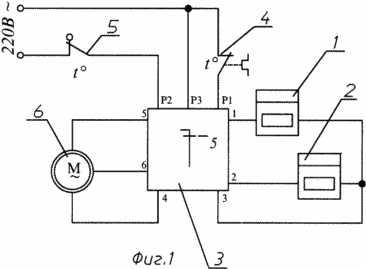
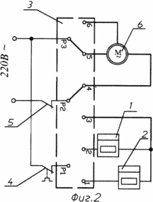
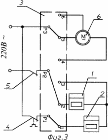
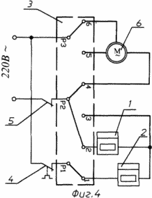
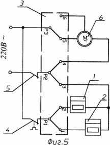
In Fig. 1 shows the general electrical diagram of the claimed fan heater, in FIG. 2 the position of the mode switch in the ventilation mode, in FIG. 3 the position of the mode switch 2 in the natural convection mode, in FIG. 4 the position of the mode switch 3 in the series connection of the heaters Forced convection, FIG. 5 shows the position of the 4 mode switch when parallel connection of heaters in forced convection mode.
The claimed fan heater (see Figs. 1, 2, 3, 4) contains the heating elements 1 and 2, version T 220 (GOST 13268-88). The first terminal 1 of the heating element 1 is connected through the contact P1 of the mode switch 3 to the thermostat 4, the second terminal of which is connected to the power supply zero. The first terminal 2 of the heating element 2 is connected in the fourth position of the switch 3 with the contact P1 of the switch 3. In the second and third position of the switch 3, the first terminal 2 of the heating element 2 is connected through the contact P2 of the switch 3 with a thermal switch 5 whose second terminal is connected to the phase of the power source. The second terminals 3 of the heaters 1 and 2 are connected and connected to the contact P2 of the switch 3. One terminal 4 of the single-phase two-speed fan motor 6 is connected to the contact P2 of the switch 3, the other terminals 5, 6 of the electric motor 6 are connected through the contact P3 of the switch 3 to the power supply zero.
THERMAL MANAGER WORKS AS FOLLOWING
In position 1 of the switch 3 (FIG. 2), the motor 6 rotates the fan (not shown). The fan heater works in ventilation mode.
With position 2 of the switch 3 (FIG. 3), the motor 6 is turned off. The first terminals 1 and 2 of the TES 1 and 2, respectively, are connected to the contacts P1 and P2 of the switch 3, respectively. The heaters 1 and 2 connected in series give off 0.25 of the total thermal power. The fan heater works in the natural convection mode.
In position 3 of the switch 3 (FIG. 4), the terminal 4 of the electric motor 6 is connected to the contact P2 of the switch 3, the terminal 6 is connected to the contact P3 of the switch 3. The fan motor 6 is turned on at the minimum speed. The first terminals 1 and 2 of the heaters 1 and 2 are connected to the contacts P1 and P2 of the switch 3, respectively. The heaters 1 and 2 connected in series give off 0.25 of the total thermal power. The fan heater works in the forced convection mode with the minimum blowing speed of the heaters.
In position 4 of the switch 3 (FIG. 5), the terminal 4 of the electric motor 6 is connected to the contact P2 of the switch 3, the terminal 5 is connected to the contact P3. The electric motor 6 is switched on to the maximum speed of rotation. The first terminals 1 and 2 of the heaters 1 and 2 are connected to the contact P1 of the switch 3, the second terminals 3 are connected and connected to the contact P2 of the switch 3. The connected heaters 1 and 2 produce the total thermal power. The fan heater operates in forced convection mode with a maximum blowing speed.
The thermostat 4 switches off the heaters after reaching the set temperature of the incoming air in the range from 0 to 40 o C. The thermoswitch 5 switches off the fan heater after reaching the maximum permissible temperature of the housing (over 110 o C).
Alternating fan operation modes allows creating comfortable conditions for a person in a wider range of ambient air temperatures. The uniformity of the load of heaters for all operating modes increases the operating life of the fan heater. Thus, the proposed technical solution has improved consumer properties in comparison with the prototype.
The company developed a prototype of the proposed fan heater.
CLAIM
A fan heater comprising electric heating elements, the first outlet of one electric heating element through the first switch of the mode switch is connected to a thermostat whose second terminal is connected to the first pole of the power source, the first terminal of the second electric heating element in one position of the mode switch is connected to the first switch of the mode switch, the second terminals of the electric heating The one-phase fan motor whose one terminals are connected to the third contact of the mode switch, is characterized in that the first terminal of the second electric heating element in the other position of the mode switch is connected through a second switch contact Modes with the thermal switch, the connected second terminals of the electric heating elements are connected to the second contact of the mode switch, the other terminal of the fan motor is connected to the second contact of the mode switch, the third contact of the mode switch is connected to the first pole of the power supply.
print version
Date of publication 25.01.2007gg



Comments
When commenting on, remember that the content and tone of your message can hurt the feelings of real people, show respect and tolerance to your interlocutors even if you do not share their opinion, your behavior in the conditions of freedom of expression and anonymity provided by the Internet, changes Not only virtual, but also the real world. All comments are hidden from the index, spam is controlled.