
| Start of section
Production, amateur Radio amateurs Aircraft model, rocket-model Useful, entertaining |
Stealth Master
Electronics Physics Technologies Inventions |
Secrets of the cosmos
Secrets of the Earth Secrets of the Ocean Tricks Map of section |
  |
| Use of the site materials is allowed subject to the link (for websites - hyperlinks) | |||
Navigation: => |
Home / Patent catalog / Catalog section / Back / |
|
INVENTION
Patent of the Russian Federation RU2208201
![]()
CERAMIC GAS BURNER AND HEAT REGENER SUPPLIED WITH THIS BURNER
The name of the inventor: VAN DEN BEMT Johannes Cornelis Antoine (NL); NOAI Kurt Johannes (NL)
The name of the patentee: DANIELI KORUS YUROP BV (NL)
Address for correspondence: 129010, Moscow, ul. B. Spasskaya, 25, p. 3, LLC "Law firm Gorodissky & Partners", Pat. EVVomsky, registration number 106
Date of commencement of the patent: 1998.11.18
A ceramic gas burner is designed for use in a combustion chamber of a heat regenerator, such as an air heater for a blast furnace. The ceramic burner is provided with a first supply port for a first fuel component, such as a combustible gas, and a second supply channel for a second fuel component, such as combustion air, wherein the first supply conduit communicates with the substantially elongated outlet opening and the second supply channel is communicated, With a second outlet opening, the last opening (s) extending substantially parallel to the first outlet and downstream thereof, a baffle that extends to two outlets, these outlets communicating directly with the combustion chamber, in addition, the baffle Is disposed between the first supply passage and the second supply channel and in which at least one of the first and second delivery channels is provided with means for creating a turbulence of the fuel component during operation while it exits through the channel (s) about which And this turbulence is such that a combustible mixture of the two components is formed upstream of the end of the partition and in its vicinity, said turbulence generating means comprising an expansion stage that is located near the outlet opening (s) of at least the first and / or Of the second feed channel, in the cross section of the channel in question, the expansion stage is provided by the partition form and continues up to the end of the partition by gradual expansion, resulting in the formation of a turbulence chamber. The invention makes it possible to provide combustion in fact at a constant location, preferably very close to the outlets.
DESCRIPTION OF THE INVENTION
The invention relates to a ceramic gas burner, especially for use in a combustion chamber of a heat recovery apparatus, such as a blast furnace heater, wherein the ceramic burner is provided with a first supply port of a first fuel component, such as a combustible gas, and a second fuel supply port of a second fuel component, such as The combustion air, the first supply path communicating with the substantially elongated outlet, and the second supply channel communicating with at least one second outlet, the latter opening (s) extending substantially parallel to the first outlet and downstream thereof , A partition that extends to two outlets, these outlets communicating directly with the combustion chamber, moreover, the partition is located between the first supply passage and the second supply channel. The invention relates to a heat regenerator provided with a ceramic burner of this type.
In the operation of a blast furnace, a plurality of air heaters are grouped together near this blast furnace, whereby it is always possible, by switching from one heater to another, hot air as a reaction component through the outlet of the heated air heater to the blast furnace. When the heater is disconnected from the blast furnace, it can be reheated by the combustion gas with a ceramic burner, whereby the hot exhaust gas passes through the combustion chamber and the heat storage shaft, wherein the heat storage chamber absorbs the heat of the hot exhaust gas, so that the heat can Then be transferred again in a subsequent stage of operation to the air, which is supplied to the air heater through the inlet.
For the efficiency of the installation, it is very important that the fuel components fed into the ceramic burner are burned as far as possible completely before the hot exhaust gas passes through the heat storage shaft. For this reason, various designs of the ceramic burner have been designed. In the above-mentioned burner of the known type, embodiments are known in which one flammable gas supply channel and one combustion air supply duct are provided. There are also known structures in which one channel for combustible gas is located centrally between two combustion air supply channels.
There are also known structures in which the outlet of the combustion air supply duct contains one opening, while it is also known to separate this opening into a number of separate openings. The latter construction is described, for example, in EP 0090096.
Although the known designs make it possible to significantly improve the combustion efficiency to be achieved, it has been found that nevertheless it is possible to further improve it. In particular, it was found that it is very important to keep the ignition of the flame as close as possible over the burner all the time. This is due to the fact that if the ignition occurs at a higher altitude as a result of the slow mixing of the fuel components, it becomes possible for a significant fluctuation in the place of combustion, leading to a pulsation of the flame, which can cause vibration of the installation as a whole.
It is therefore an object of the invention to provide distinctive characteristics by which combustion occurs virtually at a constant place, preferably very close to the outlets.
The solution that has been found at present can be used both in structures with one and two channels for feeding the second component of the fuel, and in structures in which the outlet of each supply channel is a single hole or divided into separate openings.
The invention consists in that at least one of the first and second delivery channels is provided with means for creating a turbulence of the fuel component during operation while it leaves the channel (s) in question, this turbulence being such , That a combustible mixture of the two components is formed upstream and near the end of the partition. It has been found that turbulence can be created in a simple manner if said means comprise an expansion stage that is located near the outlet (s) of at least one and / or the second supply channel in the cross section of the channel in question that the step Expansion is provided by the shape of the partition and continues up to the end of the partition by means of gradual expansion, resulting in the formation of a turbulence chamber. In the place of a sharp expansion, turbulence is created in the fuel component, which passes after this expansion into the additional space created, and this turbulence is transferred to another component of the fuel, resulting in the formation of a turbulent combustible mixture. This combustible mixture can be ignited directly at the same location due to the fact that, with turbulence, the flow velocity in the longitudinal direction of the combustion chamber is low. As a result, the generated flame can not easily be "blown away" from the burner head.
Of course, the sudden expansion should be wide enough to create sufficient turbulence. It has been found that good results are achieved if the magnitude of the expansion stage is from 20 to 35% of the original cross section of the channel in question.
It was established that the success of the new design is facilitated not only by the dimensions of the expansion stage, but also by the fact that the best results are achieved if the expansion stage continues up to the end of the partition by means of gradual expansion, resulting in the formation of a turbulence chamber. Due to the gradual expansion, the generated turbulence chamber reaches a sufficient volume to create a turbulence of a larger volume of gas and, therefore, to mix it into a combustible mixture. This additionally ensures the stability of the flame formation just above the end of the partition.
DE 2700786 describes a ceramic burner with a mixing chamber for combustible gas and combustion air that is located upstream of the combustion chamber and is separated from it by a channel with a narrow cross section. In the mixing chamber, combustion of the mixture is prevented due to this channel with a narrow cross-section. Since in the ceramic burner of the present invention, the gas and air outlets communicate directly with the combustion chamber and the turbulence generating means forms a combustible mixture upstream and downstream of the partition and the ignition of the combustible mixture begins at said means.
EP 0090096 describes a ceramic burner in which the outlets for gas and air are shaped to create turbulence from these outlets to the combustion chamber. No separate devices, such as an expansion stage for creating a turbulence of a gas-air mixture upstream of the holes and near the end of the partition, have been described. US Pat. No. 3,837,793 describes ceramic burners of the prior art, in comparison to which the present invention is an improvement.
In addition to the described ceramic burner, the invention relates to a heat regenerator, such as a blast air heater, which is provided with a gas supply inlet that is to be heated and a heated gas outlet containing a combustion chamber and a heat storage shaft, A ceramic gas burner for heating a heat regenerator, the gas burner being of the type described above.
The invention will be explained in more detail below with reference to the drawings in which:
 |
 |
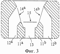 |
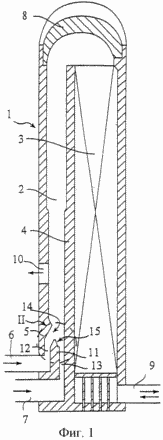
FIG. 1 shows an example of a heat regenerator, an air heater for a blast furnace.
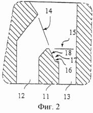
FIG. 2 is an enlarged detail of FIG. 1 of FIG.
3 shows another embodiment of this part.
1, reference 1 denotes a heat regenerator in the form of an air heater for a blast furnace. The air heater comprises a combustion chamber 2 and a heat preservation shaft 3 which are separated from each other by a wall 4. The ceramic burner 5 is located at the bottom of the combustion chamber. The combustion air for the ceramic burner is fed through the connecting hole 6 and the fuel in the form of a combustible gas is supplied through the connection hole 7. A mixture of combustion air and a combustible gas is burned in the combustion chamber 2. The combustion gases rising up in the combustion rise in the combustion chamber 2 , Are discharged through the dome 8 and then pass through the heat preservation shaft 3, which is made with refractory bricks (not shown), where they give off considerable heat to the refractory bricks. The flue gases that are cooled as a result of this action leave the air heater through the outlet 9, one of which is shown.
After the refractory bricks have been heated to a sufficient temperature, the supply of fuel and combustion air through the orifices 6 and 7 ceases, after which cold air is supplied through the discharge openings 9. This cold air then passes through the heat-retaining surface in the heat-preservation shaft 3, heats up here And then leaves the stove through the opening 10. The opening 10 is connected to a distribution system for hot air, the so-called "hot wind", to supply it to the blast furnace.
The combustible gas that is supplied through the connection hole 7 is withdrawn upwardly into the first fuel gas supply duct 13, while the connection hole 6 is connected to the second combustion air supply duct 12. The supply channels 12 and 13 are separated from one another by a partition 11.
The configuration around the upper end of the baffle 11 is indicated by reference numeral 11 and is shown in detail on an enlarged scale in FIG. The corresponding reference numerals in FIG. 1 refer to respective elements in FIG. In FIG. 2, it can be seen that the outlet 14 of the first supply channel 12 is located at a higher level and at an angle relative to the outlet 15 of the flammable gas duct 13. As a result, the air flow can pass through the gas flow, whereby they are mixed so as to form a combustible mixture.
The feed channel 13 is provided, just below the outlet 15, by an expansion stage 16 which is provided by the local constriction of the partition 11. The expansion stage 16 is adjacent to the gradual expansion 17 towards the outlet 15. As a result, a turbulence chamber 18 is formed between the expansion stage 16, 17 and the outlet 15. In the turbulence chamber 18, the intense turbulent movement that takes place just above the outlet 15 is transferred to a portion of the gas stream, whereby it is communicated to the combustion air from the duct 12. As a result, a rich combustible mixture is formed in the turbulence chamber 18 , Which has a low velocity component in the direction of the main flow through the combustion chamber 2. If this rich combustible mixture is ignited, the flame front near the free end of the partition 11 remains very stable. As a result, flame pulsation is prevented and, consequently, vibration phenomena throughout the structure are prevented. Moreover, the efficiency of combustion improves.
As mentioned above, the invention is not limited to the structure shown. In many cases, a ceramic burner is preferred, in which the two combustion air supply channels 12 a and 12 b are arranged symmetrically with respect to the supply channel 13 of the combustible gas. In this embodiment, as shown in FIG. 3, instead of one partition 11, two partitions 11 a and 11 b are provided, and there are two outlets 14 a and 14 b for supply channels 12 a and 12 b .
The same positive effect is achieved if the outlet (s) 14 (or 14 a and 14 b ) of the combustion air are divided into separate openings.
CLAIM
1. A ceramic gas burner, especially for use in a combustion chamber (2) of a heat regenerator, such as a blast furnace (1) for a blast furnace, the ceramic burner being provided with a first feed channel (13) for a first fuel component, such as a combustible gas, and (12) for the second fuel component, such as combustion air, the first supply path (13) communicating with the substantially elongated outlet (15) and the second supply channel communicating with at least one second outlet ( 14), the last opening (s) extending substantially parallel to the first outlet and downstream thereof by a baffle (11) which extends to two outlets (14, 15), these outlets (14, 15) communicating directly With the combustion chamber (2), moreover, the partition is located between the first supply channel (13) and the second supply channel (12), and in which at least one of the first and second delivery channels (12, 13) is provided Means for generating the turbulence of the fuel component during operation, while it exits through the channel (s) in question, this turbulence being such that a combustible mixture of the two components is formed upstream of the end of the partition (11) and in the vicinity of it, Said turbulence generating means comprising an expansion stage (16) that is located near the outlet opening (s) (14, 15) of at least the first and / or second supply channel, in the cross section of the channel in question, the step Expansion (16) is provided by the shape of the partition (11) and continues up to the end of the partition (11) by gradually expanding (17), resulting in a turbulence chamber.
2. A ceramic burner according to claim 1, characterized in that the value of the expansion stage (16) is from 20 to 35% of the original cross section of the channel in question.
3. A heat regenerator, such as a blast furnace for a blast furnace, which is provided with a gas supply inlet (9) to be heated, and a heated gas outlet (10), comprising a combustion chamber (2) and a heat preservation shaft 3), the combustion chamber (2) being provided with a ceramic burner (5) for heating the heat regenerator, characterized in that the ceramic burner is of the type corresponding to one of the preceding claims.
print version
Date of publication 25.01.2007gg
![]()

Comments
When commenting on, remember that the content and tone of your message can hurt the feelings of real people, show respect and tolerance to your interlocutors even if you do not share their opinion, your behavior in the conditions of freedom of expression and anonymity provided by the Internet, changes Not only virtual, but also the real world. All comments are hidden from the index, spam is controlled.