| section Home
Production, Amateur Radio amateur Model aircraft, rocket- Useful, entertaining |
Stealth master
Electronics Physics Technologies invention |
space Mystery
Earth Mysteries Secrets of the Ocean Stealth section Map |
|
| Use of material is permitted for reference (for websites - hyperlinks) | |||
Navigation: => |
Home / Products Patents / In the section of the catalog / back / |
|
INVENTION
Russian Federation Patent RU2032860
![]()
Electric heaters
Name of the inventor: Makarov VN .; Agusha VA .; Tyutin AA .; Kets NA .; Nastya's SV
The name of the patentee: Research, testing and design enterprise ventilyatorostroeniya "Turmash"; Nizhneturinsky Machine Works im.Ya.M.Sverdlova
Address for correspondence:
Starting date of the patent: 1991.08.29
Use: in electrical engineering, in particular electric air heater. The inventive tapered shirred casing heater installed radial fan 2, consisting of impeller 3, fitted on the motor shaft 4, collector 5 with a vortex guide vanes 6 fairing 7, electric heating elements 8 disposed between the housing 1 and an inner corrugated shell 9 under angle to the axis of the product. In order to cool the electric motor between the flange of the motor 4 and the inner corrugated shell 9 is formed by a ring slot.
DESCRIPTION OF THE INVENTION
The invention relates to electrical engineering, in particular to an electric heater.
Known electric heater, comprising a fan fitted with a lid having a slit for the passage of air, heating elements in the form of electric heaters installed on the suction pipe [1]
The disadvantage of this design is the presence of the entrance slit airflow fan wheel, creating a large air resistance, which reduces the effect of air stream flow of electric heating elements, and hence their heat transfer.
The closest to the technical nature of the invention is a heater, on which housing has a fan inlet, and in its cavity coaxially arranged shells and heaters installed inside the shells, with the front edge of the outer ring flange and provided with return springs [2]
The disadvantage of this design is the appearance of an additional aerodynamic drag, reducing the heat transfer coefficient of electric heaters and air heater efficiency as a whole.
These drawbacks are eliminated in the proposed construction of an electric heater.
The invention aims to increase the heat transfer and electrical heaters, respectively increasing the efficiency of the heater as a whole.
This object is achieved by the fact that the basis of the heater channel is received radial fan with tubular electric arranged concentrically around the fan impeller and at an angle to the axis of the heater, the housing and the inner shell is made corrugated heater over the entire length.
Comparative analysis of the prototype can be concluded that the proposed electric heater is characterized in that the tubular heaters are arranged concentrically with the housing and at an angle to the axis of the fan impeller, the housing and the inner shell is the heater are corrugated along its length. Thus, the claimed technical solution meets the criterion of "novelty". Analysis of the known technical solutions in the test area i.e. in electrical engineering, leads to the conclusion about the absence of these symptoms are similar to essential hallmarks of the claimed electric heater, and to recognize the claimed solution meets the criterion of "significant differences".
 |
 |
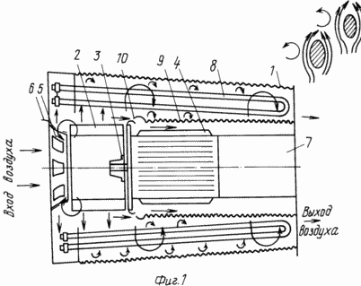
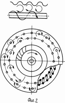
1 and 2, an electric heater shown in two projections.
The electric heater comprises a conical corrugated body 1 with the installed radial fan 2, consisting of impeller 3, fitted on the motor shaft 4, collector 5 with a vortex guide vanes 6, a fairing 7, tubular heating elements 8 disposed between the housing 1 and the inner corrugated shell 9 at an angle to the axis of the product. Between the inner corrugated shell 9 and the motor flange 4 is formed by an annular slot 10.
Cold air flow through manifold 5, having a swirl guide vane 6 is forced impeller 3, a centrifugal fan 2, an annular lattice of tubular electric heaters 8 disposed between the corrugated body 1 and an inner corrugated shell 9 at an angle to the axis of the article, is heated therein and supplied to the heated room.
Part of the cold air flow through the annular slot 10 acts to cool the motor 4, and passing between the corrugated inner shell 9 and the fairing 7 is mixed with the main stream of heated air.
The proposed electric heater operates as follows. Cold air flow previously twisted guide vanes 6 is pumped impeller 3 of the fan 2 in the annular lattice tubular electric heaters 8 which due to the presence of taper and ribbed body 1, ribbed shell 9 and the location of the electric heaters 8 at an angle to the axis of the article rotates in the annular channel twisted around tubular electric lines screw 8 while blowing them ellipsoidal airfoil and increasing as you move out of the annular channel speed air flow increases the heat-washing of the surface of tubular electric heaters, thereby increasing heat transfer.
Thus, by applying a structure of the electric heater tapered corrugated casing located therein of the radial fan arrangement tubular electric heaters around the fan impeller on its discharge side, tilt electric heater at an angle of 10 ° to the axis of rotation of the fan impeller and the presence of corrugations on the entire length of the inner shell, increases the heat transfer of tubular electric heaters, efficiency and reliability, reduced weight and dimensions of the product.
CLAIM
1. The electric heater comprising a housing having housed therein the inner shell, with the radial fan impeller and the tubular electric motor and disposed at an angle to the axis of the impeller at its discharge side, characterized in that, in order to increase the heat transfer, the housing is conical and it has corrugations along the entire length, and said shell is disposed between the impeller and electric heaters.
2. The heater of claim 1, wherein the heaters arranged around the impeller.
3. The heater of claim 1 or 2, characterized in that the placement angle of the electric heater does not exceed 10 o.
4. The heater according to claims 1 3, characterized in that the inner shell is made of corrugated.
print version
Publication date 25.01.2007gg


Comments
Commenting, keep in mind that the content and the tone of your messages can hurt the feelings of real people, show respect and tolerance to his interlocutors, even if you do not share their opinion, your behavior in terms of freedom of speech and anonymity offered by the Internet, is changing not only virtual, but real world. All comments are hidden from the index, spam control.