| Start of section
Production, amateur Radio amateurs Aircraft model, rocket-model Useful, entertaining |
Stealth Master
Electronics Physics Technologies Inventions |
Secrets of the cosmos
Secrets of the Earth Secrets of the Ocean Tricks Map of section |
|
| Use of the site materials is allowed subject to the link (for websites - hyperlinks) | |||
Navigation: => |
Home / Patent catalog / Catalog section / Back / |
|
INVENTION
Patent of the Russian Federation RU2075697
![]()
AIR HEATER
The name of the inventor: Yurmanov BN; Aleshechkina TV; Starkova LG
The name of the patent holder: St. Petersburg State University of Architecture and Civil Engineering
Address for correspondence:
Date of commencement of the patent: 1994.03.30
Use: in the field of ventilation and air conditioning. SUMMARY OF THE INVENTION: The air heater comprises an air distribution box 2 and a housing 1 in which there is a heat exchange stack of plates 4 installed in a pallet 3 forming dry and wet channels 5 and 6 for passage of external and recyclable internal air, made respectively with moisture-proof and capillary-porous coatings . From the end faces of the heat exchange plate package 4, each pair of plates alternately is closed by a plug 7 and is open at the top of the bag. From above, through the nozzles 10, tap water 8 is supplied via the supply line 9 to the porous material 8, while the tray 3 in which the heat exchange plate package 4 is disposed is provided with a overflow 11 and a discharge pipe 12. The pallet 3 is separated from the air distribution spaces 16 and 17 by dividing walls 20, And between the outer plates of the heat exchange plate pack 4 and the partitions 14 there are installed soft gaskets 15.
DESCRIPTION OF THE INVENTION
The invention relates to the field of ventilation and air conditioning.
It is known that plate heat recovery exchangers are used for heat recovery of air, the heat exchange surface of which is made of metal, glass, polymer film and other materials (Energy saving in heat supply, ventilation and air conditioning systems: Reference manual / LD Boguslavsky, V.I. Livchak, VP Titov, and others M. Stroyizdat, 1990. p.277-306). In cases where latent heat is utilized and condensate falls out, expensive non-ferrous metals are used and sometimes glass (Energy saving in heat supply, ventilation and air conditioning systems: Reference manual / LD Boguslavsky, VI Livchak, V.P. Titov et al. M. Stroyizdat, 1990. p.300). The use of glass is difficult because of its fragility. The use of different classes of plastics makes it possible to avoid these drawbacks.
Known recuperative heat exchangers have a significant disadvantage associated with the loss of condensate, which sharply increases the aerodynamic resistance. And at low negative temperatures of the outside air, the condensate formed in the channels of the exhaust air freezes, reducing the heat transfer coefficient and increasing the aerodynamic resistance of the heat exchangers (Bogoslovsky, VN, Kokorin, OY, Petrov, LV, Air Conditioning and Refrigeration, M. Stroiizdat, 1985. - p.295-296).
To ensure the operation of recuperative heat exchangers in winter conditions, either preheating the supply air to a safe temperature, or sequentially switching off part of the heat exchanger channels by means of a movable flap. In both cases, especially in the first case, the efficiency of heat utilization decreases significantly with a decrease in air temperature. Since in our country the prevailing low negative temperature of the outside air is, these measures are clearly insufficient.
The closest to the claimed technical solution is the air cooler a. from. N 1469251, cl. F 24 F 3/14, 1989. The air cooler comprises a housing with a section mounted therein. The section contains a pallet, a stack of successively mounted plates, one side of which is waterproof and the other side is capillary-porous. With successive installation of plates, alternating dry channels and moist channels are formed. Wet channels along the ends of the package are closed with plugs. In the winter operating mode the air cooler is used to heat and humidify the outside air due to the heat of the exhaust air from the room passing through this mode of operation through the dry channels. Then the heated and moisturizing air, passing through moist channels, is fed into the room.
The disadvantage of the known design is the low efficiency of utilization of the latent heat contained in the ejected air in the form of water vapor, limited operational capabilities due to increased aerodynamic drag and limiting the permissible speeds.
The task, the solution of which is directed to the invention, is to increase the degree of utilization of the latent heat of the exhaust air and increase the operational capabilities of the air heater. As a result of increasing the degree of utilization of latent heat and eliminating the condensation of water vapor on the walls of the channels, the danger of condensate freezing decreases, the aerodynamic resistance decreases, and a wider range of permissible speeds becomes possible.
The essence of the invention lies in the fact that the air heater contains an air distribution box and a housing that is rigidly fixed with a heat exchange bag installed in the pallet. The heat exchange bag is made of vertically mounted plates, one side of which is liquid-impermeable, and the other is capillary-porous, forming channels for passage of external and internal air flows. The channels are formed by installing the plates with a wettable capillary-porous side facing each other with a lumen, forming moist channels for the arrival of the recycled internal air, another pair of plates facing each other with moisture-proof layers, forms a dry channel for the passage of heated, usually outside, air. On one side of the heat exchange bag, each pair of plates forming the dry channels is closed by a plug from the entrance to the bag of moist air and is open at the top for the exit of heated dry air. On the opposite side of the bag, each pair of plates forming wet channels is closed from the end by a plug from the entrance to the dry air bag, but opens at the top for the recovery of the recycled humid air. The heat exchange plate package is rigidly installed in a water tray equipped with a overflow and a discharge pipeline. Between the outer plates of the heat exchange bag and the partitions, soft gaskets are installed.
At high temperatures of the utilized air (100 o -150 o C), the thermal conductivity of the capillary-porous material is low. Its thermal conductivity can be increased by wetting with water. To improve the wetting of the capillary-porous coating of the plates and to operate the air heater at a temperature of recycled air from 100 ° to 150 ° C, tap water is supplied from above through the nozzles onto the porous material. The porous material serves to uniformly moisten the capillary-porous coating of the plates. Uniform wetting of the plates protects them from uneven deformation in contact with hot recycled air, and prevents the transfer of large-scale droplets into the air flow. The presence of a pallet with overflow allows you to maintain a given level of water, and draining serves to empty the pallet during maintenance of the stove. The heat exchange plate pack is bounded by a casing with a partition inside, forming horizontal and vertical cavities together with the plate package, limited by lowering the dividing partitions. The presence of separating partitions will avoid contact of the air of the heated and cooled streams with water in the pan. Execution of the channels of the removed air flow from the liquid-permeable capillary-porous polymeric material, and the supply air channels from the liquid-permeable material, allows to eliminate condensation of moisture in the channels of the removed air.
Comparison of the claimed technical solution with the prototype makes it possible to establish the presence of distinctive features and conformity to its criterion "novelty".
Comparison of the proposed technical solution with other known solutions allows us to conclude that there is an inventive level, since The authors do not know from the scientific, technical and patent literature the use of air heaters of a similar design.
 |
 |
 |
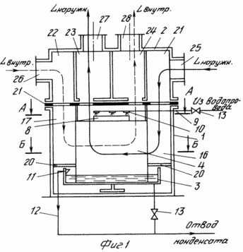
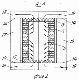
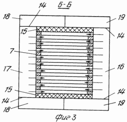
BRIEF DESCRIPTION OF THE DRAWINGS The essence of the invention is illustrated by the drawings, in which: FIG. 1 shows an air heater, a general view; 2 is a cross-sectional view of the heater according to AA; 3 shows a cross-sectional view of the heater according to B-B. The air heater comprises a housing 1 and an air distribution box 2. The housing 1 is rigidly fixed with a stack of consecutive installed plates 4 in the pallet 3, one side of which is liquid-permeable and the other side is capillary-porous. By successively installing the plates 4, alternating dry channels 5 and wet channels 6 are formed (FIGS. 2 and 3). On one side of the plate package 4, each pair of alternating plates constituting the dry channels 5 are closed by a plug 7 (FIG. 3). On the opposite side of the plate package 4, each pair of plates forming the humid channels 6 are closed by a plug 7. As a result, the moist air enters the moist channels 6 from the opposite side to the incoming dry air and exits at the top of the wet channel on the dry air inlet side, . In the upper part of the package of plates 4, a porous material 8 is installed. On top of the porous material 8 there is a supply pipe 9 with injectors 10. |
The pallet 3 is provided with a overflow 11 to maintain a predetermined water level, and a discharge pipe 12 with a valve 13 for emptying the pallet. The stack of alternating plates 4 is bounded by a housing 1 with a partition 14 inside which forms horizontal and vertical cavities together with a package of plates 4. Between the outer plates of the heat exchange bag 4 and the partitions 14, soft pads 15 are installed. The partitions 14 serve to secure the pallet 3 with the package of plates 4 to the housing 1, and divide the space between the housing 1 and the package of plates 4 on the cavities 16-19. With the vertical installation of the housing 1 and the distribution box 2, the cavities 16 and 17, which are delimited from below by dividing partitions 20, and the cavities 21 and 22 form the static pressure chambers of the respective external and internal airflow respectively, and the cavities 23 and 24 form the static exit pressure chamber, respectively, Internal flow of air. The air distribution box 2 has the inlet and outlet ports 25 and 26 of the internal air flow and the ports 27 and 28, respectively, of the outlet of the external flow and the outlet of the internal air flow.
The air heater works as follows. Through the inlet 25 to the static pressure chamber formed by the cavity 21 of the junction box 2, a cavity 16 delimited from below by the dividing baffle 20 is supplied with external air which is uniformly distributed over the dry channels 5 of the plate package 4, passing through which it is heated by the exhaust air, But also due to the latent heat of condensation of water vapor from the recycled air passing through the moist channels 6. Then, the heated air from the dry channels 5 enters the static pressure chamber formed by the cavity 23 of the junction box 2 and is fed through the branch pipe 27 into the room.
The exhaust wet and hot air from the process equipment is fed to the wet channels 6 through the nozzle 26 into the static pressure chamber formed by the cavity 22 of the distribution box 2, a cavity 10 delimited from below by the dividing partition 20. In this case, it gives heat to the supply air passing through the dry channels 5 , Due to the higher temperature and heat of condensation of water vapor. Condensation of water vapors from the recycled air becomes possible. The temperature of the air passing through the dry channels is below the dew point of the exhaust air, water condenses out of the latter, which, by wetting the capillary-porous coating of the channels 6, flows into the tray with water 3.
In order to improve the wetting of the capillary-porous coating of the plates forming the moist channels 6, and to operate the air heater at the temperature of the utilized air from 100 ° to 150 ° C, tap water is supplied from above from the nozzles 10 to the porous material 8. The water supply to the nozzles is provided by means of a supply line 9 provided with a valve 13. The porous material 8 serves to uniformly moisten the capillary-porous coating of the plates and prevents the transfer of large-scale droplets into the air flow. The drained and cooled air enters the static pressure chamber formed by the cavity 24 of the junction box 2 and is discharged through the nipple 28 into the atmosphere. The presence of a pallet 3 with overflow 11 allows to maintain a predetermined water level, and a discharge line 12 provided with a valve 13 serves to empty the pallet during maintenance of the heater. The resulting condensate from the pallet 3 is taken away for further use.
CLAIM
An air heater comprising an air distribution box, a housing with partitions and a heat exchange bag installed therein in the form of vertically mounted plates in a pallet of wettable capillary-porous material coated with a liquid-impermeable layer on one side and forming dry and moist channels for air flows muffled in pairs and Alternately from the end faces, characterized in that a supply pipeline with injectors is installed above the heat exchange package, the tray is equipped with overflow and a discharge pipeline, and soft gaskets are installed between the outer plates of the heat exchange bag and the partitions.
print version
Date of publication 25.01.2007gg


Comments
Commenting on, remember that the content and tone of your message can hurt the feelings of real people, show respect and tolerance to your interlocutors even if you do not share their opinion, your behavior in the conditions of freedom of expression and anonymity provided by the Internet, changes Not only virtual, but also the real world. All comments are hidden from the index, spam is controlled.