| Start of section
Production, amateur Radio amateurs Aircraft model, rocket-model Useful, entertaining |
Stealth Master
Electronics Physics Technologies Inventions |
Secrets of the cosmos
Secrets of the Earth Secrets of the Ocean Tricks Map of section |
  |
| Use of the site materials is allowed subject to the link (for websites - hyperlinks) | |||
Navigation: => |
Home / Patent catalog / Catalog section / Back / |
|
INVENTION
Patent of the Russian Federation RU2066023
![]()
RADIATION BURNER
The name of the inventor: Aleksandrov VA; Barybin NF; Myagkov K.G .; Popov GA; Soloviev ES; Yakushin M.I.
The name of the patent holder: Research Institute of Applied Mechanics and Electrodynamics of the Moscow Aviation Institute. S.Ordzhonikidze
Address for correspondence:
Date of commencement of the patent: 1994.09.02
Usage: for domestic and industrial needs in various heat power plants, for example, in domestic and household gas stoves, heaters, dryers, ovens. SUMMARY OF THE INVENTION: in a radial burner comprising a body 1 with a perforated cover 4 provided in the outlet section with an emitting nozzle 3 installed therein to form a distribution chamber 2 connected to the latter on a part of its surface, an injection mixer 5 arranged as a series-mounted diffuser 9 , A cylindrical pinch and an injector 8, at the entrance to which and in the area of the airway windows 7 a fuel injector 6 is installed, the injector of the mixer 8 is made to have a length exceeding 30 to 60 times the diameter of the outlet section of the nozzle 6, the diffuser 9 having a length exceeding 1.5 - 3.5 times the diameter of its outlet section, the cylindrical pinching of the injector mixer with a length of 1.0 - 3.0 of the diameter of the output section of the injector 8, is distributed in the distribution chamber 2 with a circular cross section output and a length of 0.1 - 0.3 of the diameter of its output section. The fuel injector 6 can be made multi-nozzle. The fuel injector 6 can be centrifugal, the injector mixer 5 can be made detachable. The radiation burner can additionally be provided with a fuel mixture distributor 11 located in the inlet portion of the distribution chamber 2, the fuel mixture distributor 11 can be made of deflecting elements assembled in the form of a disk.
DESCRIPTION OF THE INVENTION
The invention relates to heat power engineering, namely, to radiation radiating burners and can be used for domestic and industrial needs in various heat power devices, household and municipal gas stoves, heaters, dryers, ovens.
A known radiating burner comprising a gas chamber surrounded by a housing above which is mounted a heating plate made of a refractory thermal insulation material with a certain number of small through holes. A mesh covering the entire outer surface with a heating plate is installed above the heating plate, while the injection mixer is located parallel to the surface of the burnt ceramic. This arrangement of the injection mixer increases the hydraulic resistance of the fuel supply path, which degrades the stability of combustion at low fuel pressures (US Patent No. 3,488,137, cl. 431-329, 1970).
The closest technical solution is a radiation burner comprising a housing with a perforated cover provided with an emitting nozzle installed in it with the formation of a distribution chamber, an injection mixer connected to the latter in the area of its area, arranged in the form of a sequentially located diffuser, a cylindrical pinch and an injector , At the outlet to which a fuel injector is installed in the zone of air-inlet windows (Isserlin AS Gas burners, L. Nedra, 1966, p. 60 63, figure 22).
Combustion of the fuel-air mixture in this burner occurs mainly in the near-surface zone inside the channels and on the surface of the radiating nozzle, and afterburning of the unburned components in the space between the nozzle and the perforated cover and near the surface of the incandescent perforated cover. However, the location of the injector mixer along the surface of the radiating nozzle increases the hydraulic resistance of the fuel mixture supply pathway, degrades the stability of combustion at low fuel pressures, and reduces the operating pressure range of the burner.
The aim of the invention is to increase the environmental and operational characteristics of the burner by increasing the stability of combustion in a wide range of fuel pressure changes, reducing the hydraulic resistance of the fuel mixture supply path, which in turn ensures more complete combustion of fuel and reduces the amount of CO in the combustion products. In addition, the solution of this problem extends the functionality of the radiation burner.
The above object is achieved in that, in a radiation burner comprising a housing with a perforated cover provided in the outlet section with a radiating nozzle installed therein to form a distribution chamber, an injection mixer connected to the latter in the form of a series-mounted diffuser, a cylindrical clamp And an injector at the outlet to which a fuel injector is installed in the area of the airway windows, the injector of the mixer is made with a length exceeding 30 times the diameter of the outlet section of the injector nozzle, a diffuser with a length exceeding 1.5 times the diameter of its output section, A cylindrical pinhole length of 1.0 3.0 of the diameter of the outlet section of the injector, and the distribution chamber is designed with a circular cross-sectional exit length of 0.1 0.3 of the diameter of its outlet section.
In addition, the fuel injector is made multi-nozzle.
In addition, the fuel injector is centrifugal.
In addition, in the radiation burner the mixer is made detachable.
Moreover, the burner is further provided with a fuel mix distributor located in the inlet section of the distribution chamber. In this case, the distributor is made of deflecting elements assembled in the form of a disk.
To ensure the stable operation of the radiation burner on the injector principle with the regulation of the fuel mixture pressure in wide ranges with high operational and environmental characteristics allowing the use of these burners in household gas stoves, it is necessary to ensure good injection, mixing and distribution of the fuel mixture in a short section and with minimal hydraulic Resistance, combustion of the fuel mixture and reduction of CO. The permissible norm of CO for domestic burners is 0.01
The main objectives of the invention are solved by performing an injector mixer of a certain size, which is confirmed by experimental studies. Performing a mixer injector longer than 30-60 times the nozzle nozzle outlet nozzle diameter determining the amount of ejected air, mixing quality and stoichiometry, allows to provide high ecological characteristics within the specified range. The experimentally obtained value of CO is 0.006, which is significantly lower than the permissible norm. The length of the mixer injector exceeding the diameter of the nozzle nozzle outlet section is less than 30 times, characterized by insufficient air ejection, incomplete combustion of the fuel mixture and a sharp increase in CO content exceeding permissible 0.01
Execution of the injector length of the mixer exceeding the diameter of the nozzle nozzle outlet section by more than 60 times leads to a deterioration of combustion due to excess air, an increase in the CO content exceeding 0.01 and the detachment of the combustion zone from the radiating nozzle.
Mixing zone The cylindrical punching of the injection mixer is made 1.0 1.0 times the diameter of the outlet section of the injector, determines the quality of mixing of fuel and air, and the uniformity of the distribution of the gas-air ratio over the surface of the radiating nozzle and, therefore, provides high environmental characteristics of the radiation burner. For the specified range of cylindrical pinhole length, the experimental CO content obtained in the combustion products is ![]() 0.008 The ratio of the length of the cylindrical pinch is less than 1.0 leads to poor mixing of fuel and air, large uneven distribution of the fuel mixture over the surface of the burning radiating plate, and a sharp increase in the CO content to 0.05 and higher.
0.008 The ratio of the length of the cylindrical pinch is less than 1.0 leads to poor mixing of fuel and air, large uneven distribution of the fuel mixture over the surface of the burning radiating plate, and a sharp increase in the CO content to 0.05 and higher.
The ratio of the length of the cylindrical pinch exceeds 3 leads to an increase in the hydraulic resistance of the tract and, correspondingly, to an increase in the dimensions of the radiation burner.
The outlet section of the injection mixer is made in the form of a diffuser that exceeds the diameter of its outlet cross section by a factor of 1.5 to 3.5 times, which ensures the quality of mixing of fuel and air and uniformity of the flow velocity field over the surface of the radiation burner. This is confirmed by the obtained CO content ![]() 0.008 The length of the diffuser is less than the ratio of 1.5 resulting in a significant unevenness in the speeds of the fuel mixture in the radiating nozzle and uneven CO content in combustion products exceeding the CO value in accordance with GOST.
0.008 The length of the diffuser is less than the ratio of 1.5 resulting in a significant unevenness in the speeds of the fuel mixture in the radiating nozzle and uneven CO content in combustion products exceeding the CO value in accordance with GOST.
Execution of the length of the diffuser greater than the ratio 3.5 leads to an increase in the hydraulic resistance and, as a consequence, to an increase in the dimensions of the radiation burner. Execution of the distribution chamber with an exit section in the form of a circle and a length of 0.1 0.3 from the diameter of the output section ensures distribution of the mixture around the periphery of the radiating nozzle and a high quality of combustion in this zone.
Execution of the length of the distribution chamber with a ratio of less than 0.1 leads to a reduction in the area of the cross-section for the fuel mixture, and a decrease in the quality of combustion. The CO content increases and exceeds 0.1. The length of the distribution chamber with a ratio greater than 0.3 leads to a significant increase in the dimensions of the product.
The use of a multi-nozzle or centrifugal fuel injector in a radiation burner significantly increases the air injection ratio provided that the fuel and air mix well, which leads to an expansion of the range of specific thermal power, and, consequently, to an increase in the range of thermal powers of the radiation burner.
The execution of the radiator burner plug-in mixer provides replacement or repair of the burner, but also provides access to the fuel injector for its replacement or repair.
At large thermal powers and large diameters of the radiating nozzle, a fuel mix distributor is installed in the inlet section of the distribution chamber, which is in particular made of deflecting elements assembled into a disc shape deflecting the flow of the fuel mixture towards the periphery, with additional stirring of the fuel mixture and Uniform distribution over the surface of the radiating nozzle.
The implementation of the injection mixer in the specified proportions of the length of its sections provides reliable combustion, reduces the hydraulic resistance of the tract, improves the ecological characteristics of the radiation burner.
 |
 |
 |
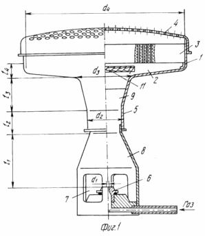
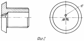
In Fig. 1 shows a radiation burner; In Fig. 2 multi-nozzle fuel injector;
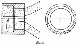
In Fig. 3 centrifugal fuel injector.
The radiation burner comprises a hollow body 1 with a distribution chamber 2 at the output portion of which a radiating nozzle 3, a perforated cover 4 and an injection mixer 5 with a fuel injector 6 installed in the inlet to the distribution chamber 2 are arranged in series, The portion of the injection mixer 5 is made in the form of an injector 8 of length l 1 exceeding the diameter of the nozzle nozzle outlet section d1 by 30-60 times, and the outlet portion of the injection mixer 5 is made in the form of a diffuser 9 of length l 3 exceeding 1.5 to 3.5 Times the diameter of its outlet cross-section d 3 , wherein the cylindrical pinch is made with a length l 2 of 1.0 3.0 of the diameter of the outlet section of the injector d 2 .
The distribution chamber 2 is provided with a circular exit section and a length l 4 of 0.1 0.3 of the diameter of the outlet section d 4 .
The fuel injector 6 can be made multi-nozzle with outlet apertures 10.
In addition, the fuel injector 6 can be made centrifugal.
To ensure repair and replacement of the components of the radiation burner, the injection mixer 5 can be made detachable. In the inlet section of the distribution chamber 2, the fuel mixture distributor 11 is installed, which is in particular made of deflecting elements assembled in the form of a disk.
RADIATION BURNER WORKS AS FOLLOWING
The fuel flows out of the nozzle 6. The jet that forms when the jet runs out at a high speed ejects the required amount of air through the air inlet windows 7 in the area of the injector 8. Then, the fuel and the ejected air are mixed in the injection mixer 5. The resulting fuel-air mixture is inhibited and mixed in the diffuser 9 of the injection mixer And through the distributor 2 enters the channels of the radiating nozzle 3. Combustion of the mixture takes place at the mouth of the channels and on the surface of the radiating nozzle 3. Afterburning of the unburned fuel mixture occurs in the space between the nozzle 3 and the perforated cover 4 and near the perforated cover 4.
The use of multi-nozzle fuel nozzles 6 or centrifugal allows significantly increasing the air injection ratio provided that the fuel and air are mixed well.
The distributor of the fuel mixture 11 allows further mixing of the fuel mixture, deflecting the fuel mixture towards the periphery of the radiating nozzle 3.
The proposed design of the injector mixer of the radiation burner, made in the declared sizes, provides a good mixture formation with its short length and minimal hydraulic resistance to the fuel mixture flow, which ensures the stable operation of the radiation burner, which increases the environmental and operational characteristics of the burner by increasing the stability of combustion in a wide range of pressure changes Fuel.
CLAIM
A radiation burner comprising: a housing with a perforated cover provided with an emitting nozzle installed in the outlet region to form a distribution chamber, an injection mixer connected to the latter in a section of its cross-section, configured as a series-mounted diffuser, a cylindrical clamp and an injector, at the inlet In which a fuel injector is installed in the zone of air inlet windows, characterized in that the injector of the mixer is made to be 30 to 60 times the diameter of the outlet section of the nozzle of the injector, the diffuser having a length exceeding 1.5 times the diameter of its outlet section, Length of 1,0 3,0 of the diameter of the output section of the injector, and the distribution chamber is made with an exit section in the form of a circle and a length of 0.1 0.3 diameter of its output section.
2. A burner according to claim 1, characterized in that the fuel injector is made multi-nozzle.
3. A burner according to claim 1, characterized in that the fuel injector is centrifugal.
4. A burner according to claim 1, characterized in that the mixer is made detachable.
5. A burner according to claim 1, characterized in that it is further provided with a fuel mix distributor located in the inlet portion of the distribution chamber.
6. A burner according to claim 5, characterized in that the distributor is made of deflecting elements assembled in the form of a disk.
print version
Date of publication 19.03.2007gg
![]()

Comments
Commenting on, remember that the content and tone of your message can hurt the feelings of real people, show respect and tolerance to your interlocutors even if you do not share their opinion, your behavior in the conditions of freedom of expression and anonymity provided by the Internet, changes Not only virtual, but also the real world. All comments are hidden from the index, spam is controlled.