| section Home
Production, Amateur Radio amateur Model aircraft, rocket- Useful, entertaining |
Stealth master
Electronics Physics Technologies invention |
space Mystery
Earth Mysteries Secrets of the Ocean Stealth section Map |
|
| Use of material is permitted for reference (for websites - hyperlinks) | |||
Navigation: => |
Home / Products Patents / In the section of the catalog / back / |
|
INVENTION
Russian Federation Patent RU2059162
![]()
SYSTEM HEAT CONSUMERS
Name of the inventor: Nikolay Dmitriev T.; Yahno Victor Anisimovich; Marchanukov Edward Tatlustanovich; Buguruslan Valentin V.; Moskalenko Alexander A.; Schalke Igor Fedorovich
The name of the patentee: Nikolai Dmitriev T.; Yahno Victor Anisimovich; Marchanukov Edward Tatlustanovich; Buguruslan Valentin V.; Moskalenko Alexander A.; Schalke Igor Fedorovich
Address for correspondence:
Starting date of the patent: 1994.07.01
Use: in the field of heat supply and is intended for heating and hot water consumers. The system comprises one heat generator formed as a vortex tube with a tangential inlet and a coolant through a nozzle confuser. The heat source is connected to the drive boosters 6 7 coolant flow, but also through lines 8, 9, 10 and shut-off valves handling 11, 12, 13 - 16 with the consumers.
DESCRIPTION OF THE INVENTION
The invention relates to a heat supply and can be used for heating and hot water supply of any consumer of heat, especially in those areas in which, for various reasons can not accommodate heat generators operating at both the liquid and solid fuel as well, and where there are no centralized sources heating.
Known heat supply system or central heating systems and fuel supply, comprising a boiler (heat generator) or the heating system, a closed loop coolant flow (eg, water) with heat exchangers, heat consumers (heating appliances, hot water analysis points, etc.), feeding reverse and return piping, expansion tank, shut-off and control valves and automatic control system [1]
However, these central heating systems are characterized by considerable dimensions heat generators, large metal and material capacity, require considerable space for their placement, but also provide a significant amount of fuel.
Known and heating systems in which heat generators are powered by the mains [2]
However, as a rule, use local elektroteplogeneratory, and where applicable capacitive electric boilers, and they spent a significant amount of metal.
Known heating system in which heat is obtained by the processes taking place while overcoming local coolant flow resistances [3]
But these systems are cumbersome, are difficult to adjust the pressure and temperature of the coolant.
The closest analogue, taken as a prototype, is a hot-water heating system [4] contains a closed loop circulation of the coolant-water heat generator, distribution tank, consumers heat pump is fed back and the connecting piping, valves and control valves and an automatic coolant temperature control.
However, this system suffers from a large material and metal content, the need to allocate special areas for heat generator and to provide the latter with fuel.
The purpose of the invention to create a heating system with a heat source, which would be distinguished by reliability, practically does not require special areas, has low material consumption, not required to provide fuel and could be placed anywhere, even remote place. Furthermore, heating system should be easily controlled for temperature and pressure coolant.
The proposed consumer heating system heat source is in the form of a vortex tube with a tangential supply of coolant through the nozzle and konfuzor of stimulus coolant flow. And to control the temperature and pressure of the coolant used bypass line with bypass coolant from a supply in the return pipe and and an automatic coolant temperature control to the control unit.
 |
 |
 |
 |
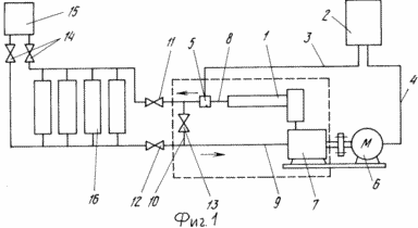
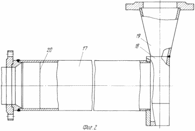
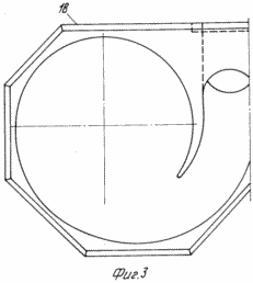
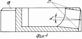
FIG. 1 is a schematic diagram of heat supply systems; Figure 2 vortex pipe section; Figure 3 injector; 4 is the same section.
heat supply system includes a heat source 1, the control unit 2 connected to the control circuits 3, 4, 5 temperature sensor and actuator 6 7 facialiator coolant flow, feed 8, 9 and reverse the connecting pipes 10, shut-off and control valves 11-14, the expansion tank 15 coupled with the consumer 16.
The temperature sensor is located on the supply pipe 8 for the heat generator 1, which is designed as a vortex tube 17 to the nozzle 18 and 19. The output confuser vortex tube 17 is installed damper 20 speed. Tangential supply of coolant is provided at an inclination angle ![]() inlet nozzle orifice 18, such as its chamfered inner surfaces 21 (Figure 4).
inlet nozzle orifice 18, such as its chamfered inner surfaces 21 (Figure 4).
heating system works as follows. When the actuator 6 control unit 2 starts and 7 stimulus motion directs the flow of liquid coolant (water, its solutions, and others.) konfuzor through 19 in the nozzle 18, which is the formation of a vortex flow of the pipe fluid 17. Fluid repulsed from the nozzle wall 18 and receives a rotary motion, rotating, progressively moves along the pipe 17, creating a vacuum inside the tube and thus releasing thermal energy. At the outlet of tube 17 is set speed absorber 20 which dampens rotational movement. Fluid enters through shut-off control valves 11, 12, 13 and conduit 16. Valves 8 user 13 can adjust the amount of liquid supplied to the consumer 16, and a reheating via conduits 10, through the booster 9 in the heat generator 7 motion 1. Expansion tank 15 to compensate for fluid leakage from the system.
Sensor temperature and 5 associated therewith control 3 thermal relay circuit control unit 2 provides the activation and deactivation of the system in a given temperature range.
The system of a small circle of liquid circulation may be formed by a shut-off and control valves 11, 12, 13 for pre-heating system.
The system has a simple design, simple and reliable in operation.
CLAIM
SYSTEM heat supply, comprising a closed circulation loop heat transfer fluid comprising a heat source, stimulus motion coolant driven, expansion tank, the back and the connecting piping, valves and control valves and an automatic coolant temperature control with a temperature sensor placed on the supply pipeline for the heat source and chains control, characterized in that the automatic coolant temperature control further comprises a control unit coupled to control circuit with a temperature sensor and actuator stimulus coolant flow, wherein the heat source is in the form of a vortex tube with a tangential inlet coolant through the confusor and the nozzle of stimulus movement, wherein a bypass line with a shut-off and control valves communicates with the flow and return pipe with bypass coolant to heat consumers, and the coolant outlet of the vortex tube is placed damper speed.
print version
Publication date 29.01.2007gg


Comments
Commenting, keep in mind that the content and the tone of your messages can hurt the feelings of real people, show respect and tolerance to his interlocutors, even if you do not share their opinion, your behavior in terms of freedom of speech and anonymity offered by the Internet, is changing not only virtual, but real world. All comments are hidden from the index, spam control.