| Start of section
Production, amateur Radio amateurs Aircraft model, rocket-model Useful, entertaining |
Stealth Master
Electronics Physics Technologies Inventions |
Secrets of the cosmos
Secrets of the Earth Secrets of the Ocean Tricks Map of section |
|
| Use of the site materials is allowed subject to the link (for websites - hyperlinks) | |||
Navigation: => |
Home / Patent catalog / Catalog section / Back / |
|
INVENTION
Patent of the Russian Federation RU2244214
![]()
OVEN FOR WASTE INCINERATION
The name of the inventor: VU Kun-Cheng (TW)
The name of the patent holder: VU Kun-Cheng (TW)
Address for correspondence: 103735, Moscow, ul.Ilinka, 5/2, OOO "Soyuzpatent", Pat. LIYatrova
Date of commencement of the patent: 2000.06.09
The incinerator includes at least one waste bogie, an oven body having a lower and upper combustion chamber. The waste trolley is transported through the furnace body, so that the waste immersed on the trolley can be ignited in the lower combustion chamber. The gaseous combustion products formed in the lower combustion chamber pass into the upper combustion chamber and are heated therein. The irrigation tank for receiving combustion gases is connected to the upper combustion chamber. In the irrigation tank, an aqueous mist is sprayed into the combustion gases to produce aerated water. The aerated water and the combustion gases leaving the irrigation tank are cooled when passing into the tank connected to the cooling means. The aerated water from the reservoir is pumped to the upper level of the waterfall tank to create a water flow down the cascades inside the waterfall tank. The combustion product outlet unit is connected to the upper end of the waterfall tank for suction and discharge of combustion gases. The technical result: increasing the degree of purification of combustion products.
DESCRIPTION OF THE INVENTION
The present invention relates to a waste incineration area, in particular to a waste incinerator, which produces combustion gases with a lower content of toxic substances.
In recent years, industrial waste and garbage are usually eliminated by burning. During combustion, the combustion gases are released into the atmosphere through the incinerator tube. However, combustion gases normally contain toxic substances, such as dioxins, which lead to serious air pollution (US 4944236 A, July 31, 1990).
Thus, it is an object of the present invention to provide a waste incinerator that emits gaseous combustion products with a lower content of toxic substances.
Accordingly, the incinerator includes at least one waste trolley adapted for loading waste into the furnace. The furnace body has a bogie entrance, a trolley exit, a lower combustion chamber located between the inlet and outlet for the bogies and connected thereto, and an upper combustion chamber located above and connected to the lower combustion chamber. A transport means is provided for transporting the bogies for loading waste through the furnace body from the bogie entrance to the bogie exit. An ignition means is provided in the lower combustion chamber of the furnace body for igniting the waste loaded in the cart when the cart is transported through the furnace body. In the upper combustion chamber, a gas heating means is provided for heating the combustion gases generated by burning the waste in the lower combustion chamber. An irrigation tank is connected to the upper combustion chamber for receiving combustion gases. In the irrigation tank, a spraying means is provided for spraying the water mist into the combustion gases and creating aerated water in the irrigation tank. A cooling means is connected to the irrigation tank to cool the aerated water flowing out of the irrigation tank. A reservoir for receiving aerated water and combustion gases leaving the cooling means is connected to the cooling means. The waterfall tank has a lower level connected to the tank and an upper level located above the tank. A pumping means is provided for injecting aerated water from the reservoir to the upper level of the waterfall tank and for discharging the aerated water at the upper level of the waterfall tank to create a water flow falling down the cascades inside the waterfall tank, which flows back to the reservoir at the lower level of the waterfall tank. An outlet block is connected to the upper level of the waterfall tank to suck off the combustion gases from the waterfall tank and discharge the combustion gases.
BRIEF DESCRIPTION OF THE DRAWINGS
Other features and advantages of the present invention are apparent from the following detailed description of preferred embodiments with reference to the accompanying drawings in which:
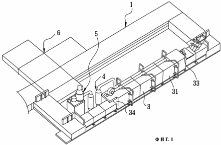
FIG. 1 shows a waste incinerator according to a preferred embodiment
Of the present invention in an isometric view.
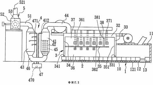
FIG. 2 is a schematic view of a preferred embodiment. FIG.
 |
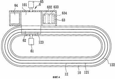 |
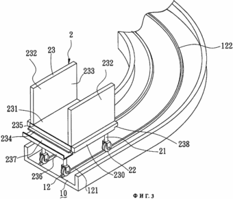
FIG. 3 shows an isometric view of a waste trolley and a rail element according to a preferred embodiment; FIG. FIG. 4 shows a block for removing debris, according to a preferred embodiment, in plan view.
 |
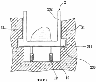 |
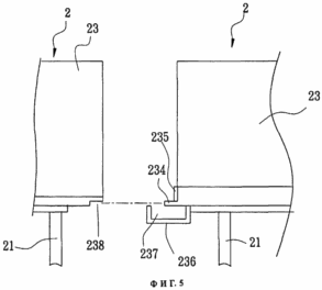
FIG. 5 shows the arrangement of two adjacent waste bogies according to a preferred embodiment; FIG. 6 shows one of the bogies for loading waste during transport through the furnace body, according to a preferred embodiment.
 |
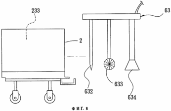 |
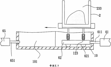
FIG. 7 shows a waste trolley during entry into the unit for removing residues according to a preferred embodiment; FIG. FIG. 8 illustrates the operation of a device for cleaning residues in a unit to remove residues.
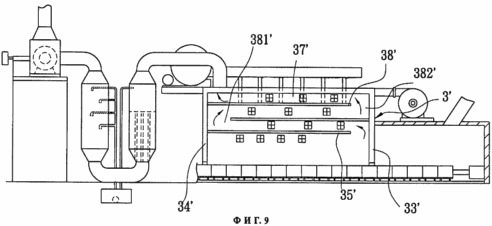
9 is a modified embodiment of a waste incinerating furnace according to the present invention.
DETAILED DESCRIPTION OF PREFERRED EMBODIMENTS
The waste incinerator of the present invention is designed to destroy industrial waste and debris and contaminated sludge in rivers and lakes. As shown in FIGS. 1 to 3, the incinerator according to a preferred embodiment of the invention includes a transport unit 1, a plurality of waste bogies 2, a furnace body 3, a combustion gas exhausting unit 4, an exhaust unit 5 Gaseous combustion products and a unit 6 for removing residues.
The transport unit 1 includes an annular transport channel 10 filled with water, a rail element 12 extending along the transport channel 10 and a lid 11 for closing the transport passage 10.
The rail element 12 has an initial portion 121 and a terminal portion 122 connected to the initial portion 121.
The carriages 2 are arranged in series on the rail element 12 in the channel 10 to move along the rail element 12. The first pushing mechanism 13 is provided in the initial portion 121 for pushing the carriages 2 and moving along the channel 10 from the initial portion 121 towards the end portion 122. Each bogie 2 has a support frame 21 provided with wheels 22 for moving along the rail element 12. The wheels 22 are immersed in water that fills the channel 10 to prevent damage to the wheels 22 due to the high temperature in the furnace casing 3. Each waste trolley 2 has a waste loading portion 23 forming a waste disposal space 233. The waste loading portion 23 includes a horizontal bottom plate 231 mounted on the support frame 21 and a parallel pair of side plates 232 that protrude upward from the lower plate 231 and which cooperate with the lower plate 231 to form a waste loading space 233. Thus, the waste trolley 2 is open in front, behind and above. The lower plate 231 has lateral edge portions provided with guide protrusions 230 that protrude, respectively, from the side plates 232. The height of the waste disposal part 23 of each trolley 2 is preferably less than 0.6 m to ensure complete combustion of the waste therein. In this embodiment, the size of waste disposal part 23 is 1.8 m × 1.0 m × 0.25 m.
As shown in FIGS. 3 and 5, the lower plate 231 of each waste bogie 2 is provided at its front end with a heat resistant buffer plate 235 and an edge 234 that projects forward from the front end. The elongate collector member 236 is attached to the front end of the lower plate 231 from the underside and projects forward with respect to the projecting rib 234 and is located below it. The collecting element 236 has a U-shaped cross-section and forms a collector cavity 237 open upward. The lower plate 231 of each waste bogie 2 is further provided with a cut-off portion 238 at the rear end for receiving, without a gap, the projecting rib 234 of the next waste bogie 2, so that the trailing end is in contact with the buffer pad 235 of the second waste bogie 2. The collecting element 236 collects waste that falls from two adjacent waste bogies 2 and prevents this waste from entering the conveying channel 10.
As shown in FIGS. 1, 2 and 6, the furnace body 3 is constructed above the rail element 12 near the initial portion 121 and is made of a refractory brick. The furnace body 3 has a length of about 30 m and includes a pair of parallel side walls 31 which are formed with guide grooves 311 to receive the guide projections 230 of the waste bogies 2. In addition, the furnace body 3 has an upper wall 32 connecting the upper ends of the side walls 31, the front wall 33 near the initial portion 121 of the rail element 12 which is provided with an input 331 for loading the waste trolley into the furnace casing 3, the rear wall 34 opposite the front Wall 33 provided with a bogie outlet 341 which provides the output of the bogie trucks 2 for loading waste from the furnace body 3 and a horizontal baffle 35 for dividing the interior space of the furnace body 3 into an upper combustion chamber 37 and a lower combustion chamber 36. The baffle 35 has a rear end connected to the rear wall 34 and a front end that forms a gap 351 with the front wall 33. The gap 351 connects the lower combustion chamber 36 to the upper combustion chamber 37. The lower combustion chamber 36 is provided with a plurality of ignition means 361 on the side wall 31. The ignition means 361 can spray fuel onto the waste immersed on the waste bogies 2 that enter the furnace body 3 for incinerating the waste. The upper combustion chamber 37 is provided with a plurality of vertical heating plates 38 that are spaced apart to heat the combustion gases that are generated by incineration in the lower combustion chamber 36. In this embodiment, each first, third and fifth heating plate 38 has a lower end attached to the partition 35 and an upper end located at a distance from the top wall 32 forming the upper air passage 381 with the top wall 32. Each second and fourth plate 38 Has an upper end attached to the upper wall 32 and a lower end located at a distance from the partition 35 forming a lower air passage 382 with the partition 35. The upper combustion chamber 37 is provided with a plurality of burners 371 on the side walls 31 for heating the heating plates 38.
The combustion gas exhausting unit 4 is located in the vicinity of the furnace body 3 for treating the combustion gases exiting the furnace body 3. The combustion gas exhausting unit 4 includes an irrigation tub 41 having an upper end connected to the upper combustion chamber 37 through a first conduit 44 for receiving combustion gases exiting the upper combustion chamber 37. In the irrigation tank 41, a spray means 412 is provided for spraying the water mist into the combustion gases entering the irrigation tank 41 to create aerated water in the irrigation tank 41. The cooling tank 42 has an upper end connected to the lower end of the irrigation tub 41 and is provided with transition Pipes 45 connected to the irrigation tank 41 to allow the aerated water and combustion gases to flow from the irrigation tank 41. The cooling tank 42 is provided with a condensing means that contains circulating condensation moisture to cool the combustion gases and aerated water passing through the transfer tubes 45. The transfer tubes 45 are connected to one end of the tank tube 46 at the lower end of the cooling tank 42 to allow passage of aerated water and combustion gases to the tank tube 46. The reservoir 47 is disposed below the reservoir tube 46 and is connected thereto to receive aerated water. The lower end of the waterfall tank 43 is connected to the other end of the reservoir tube 46. The upper end of the waterfall tank 43 is located at a level that is significantly higher than the level of the reservoir 47. A pump 470 and a supply pipe 471 with several nozzles for injecting aerated water from the reservoir 47 to the upper level of the waterfall A tank 43 and aerated water outlet at the upper end of the waterfall tank 43 to create a downward flow of water within the waterfall tank 43 that flows back to the tank tube 46 and the reservoir 47 through the lower end of the waterfall tank 43.
The combustion product outlet unit 5 is connected to the upper end of the waterfall tank 43 through the second pipe 51 and includes a fan casing 52 in which an exhaust air fan 53 is installed, an output member 521 projecting upward from the fan casing 52. The exhaust air fan 53 creates a counterpressure at the upper end of the waterfall tank 43 for sucking the combustion gases from the waterfall tank 43 and discharging the combustion gases through the outlet member 521.
The back pressure is preferably in the range of 0.8 to 0.9 atmospheres. If the backpressure is less than 0.8 atmospheres, the flow rate of the combustion gases is too high and may have a negative effect on their decomposition and cooling. If the back pressure is above 0.9 atmospheres, the combustion gases can not flow freely through the unit 4 to remove the combustion gases and the combustion product outlet unit 5.
As shown in FIGS. 4, 7 and 8, the rail element 12 has a movable section 123 which is formed on a movable platform 62 provided with wheels 621 at its lower part. The residue removal unit 6 has a working space 101 formed adjacent to the rail element 12 to allow the platform 62 to move therein. The residue removal unit 6 further has a residue cleaner 63 and a residue collector 64 that are located on opposite sides of the front end of the worker Space 101. Each waste trolley 2 after exiting the furnace body 3 through the trolley exit 341 (see FIG. 2) is transported to the movable section 123 on the platform 62 to move together with the platform 62 to and from the work space 101. A second pushing mechanism 61 is provided within the channel 10 which has a pusher 611 for pushing the platform 62 into the working space 101. A third pushing mechanism 65 is provided adjacent to the working space 101 opposite to the second pushing mechanism 61 and provided with a pusher 651 for pushing the platform 62 from the working space 101 back Into the duct 10. The residue remover 63 includes a scraper plate 632, a brush 633 and a vacuum cleaner 634. During operation of the residue removal unit 6, the residue remover 63 moves to the waste disposal space 233 from the open front side when the waste trolley 2 Is inserted into the working space 101. The scraping plate 632 scrapes the combustion residues from the walls of the trolley 2 to load the waste into the residue collector 64. Brush 633 cleans the combustion residues from the trolley 2 to load the waste into the waste collector 64. The vacuum cleaner 634 sucks the remaining combustion residues from the waste bogie 2 to complete the operation to remove the combustion residues.
As shown in FIG. 2, the incinerator according to the present invention operates in the following manner: firstly, a plurality of consecutive carriages 2 are loaded on top of waste in the initial portion 121 of the rail element 12, and the first pushing mechanism 13 is intermittently pushed to move along the rail element 12 into the furnace casing 3 via the cart entrance 331. The ignition elements 361 in the lower combustion chamber 36 spray the fuel onto the waste bogies 2 and ignite the flame in the lower combustion chamber 36 to incinerate the waste loaded onto the trucks 2. The incineration time is preferably about 1 hour to prevent incomplete combustion. In addition, during the combustion of the waste, an exhaust air fan 53 is provided to provide a backpressure in the range of 0.8 to 0.9 atmospheres to normalize the flow of the combustion gases generated in the lower combustion chamber 36 into the upper combustion chamber 37 through the gap 351. In this Time, the heating plates 38 are heated in the upper combustion chamber 37 to heat the combustion gases entering the upper combustion chamber 37. The gaseous products of combustion during their heating by means of heating plates 38 pass through the upper and lower air passages 381, 382 towards the first pipe 44. Temperatures and operating periods in the upper and lower chambers 37, 36 depend on the type of waste to be burned. Typically, the temperature in the lower combustion chamber 36 is maintained between 900 and 1500 ° C, while the temperature in the upper combustion chamber 37 is maintained between 1200 and 1800 ° C. For example, when the waste that is mercury-containing sludge is eliminated, the temperature in the lower combustion chamber 36 is 900 ° C, while the upper combustion chamber 37 is maintained at 1200 ° C. In the case where the waste to be disposed of is plastic, the temperature in the lower combustion chamber 36 is increased to about 1200 ° C, and the temperature in the upper combustion chamber 37 is about 1500 ° C. The burning time in the upper combustion chamber 37 for heating the combustion gases is generally maintained at approximately 7 seconds.
As shown in FIGS. 1, 2 and 4, after the combustion operation in the furnace body 3, the combustion residues are left on the waste bogies 2. The waste transport carts 2 are conveyed from the furnace body 3 through the outlet 341 by the discontinuous pushing action of the first pushing mechanism 13 towards the block 6 to remove the combustion residues. When one of the waste bogies 2 hits the platform 62, it is introduced into the working space 101 together with the platform 62 under the action of a second pushing mechanism 61. At this time, the residue remover 63 moves to the waste disposal space 233 to move most of the combustion residues To the residue collector 64 and to suck off the remainder of the residues and ash using the vacuum cleaner 634. Thereafter, the carriage 2 is withdrawn from the working space 101 together with the platform 62 under the action of the third pushing mechanism 65 and returned back to the channel 10 for movement along the rail element 12 .When the trolley 2 is transported back to the initial portion 121 through the end portion 122 along the rail member 12, waste is again loaded into the trolleys into the waste loading space 233 to prepare the next combustion operation.
On the other hand, as shown in FIG. 2, the combustion gases heated in the upper combustion chamber 37 pass through the pipe 44 to the irrigation tank 41.
The spray 412 sprays the water mist into the combustion gases in the irrigation tank 41. The aerated water and the combustion gases are then passed through the cooling tank 42 for cooling by a condensing means in the cooling tank 42 and then passed to the tank tube 46. The aerated water is collected In the tank 47 under the tank tube 46, while the combustion gases continuously flow into the waterfall tank 43 from the lower level to the upper level of the waterfall tank 43 by sucking the exhaust air fan 53. The aerated water collected in the tank 47 is pumped out and fed to The upper level of the waterfall tank 43 by the pump 470 and the supply pipe 471 that enters the waterfall tank 43 and discharged at the upper level of the waterfall tank 43. Thus, the combustion gases flow through the cascading downward flow of water created in the waterfall tank 43. This reduces the temperature of the combustion gases from about 900 ° C. to 200 ° C. for about 0.5 seconds. Thus, the temperature of the combustion gases rapidly falls in the range of 400 to 250 ° C., in which carbon, hydrogen and chlorine are prevented from being combined in water-insoluble and poisonous substances such as dioxins. In addition, by interacting with the heating plates and heating in the upper combustion chamber 37, the combustion gas molecules can disintegrate into smaller molecules, most of which are mixed with water as it passes through the irrigation tank 41 and collected in the reservoir 47.
In the event that the waste to be eliminated is a liquid waste, the waste is placed in a container having dimensions corresponding to the dimensions of the waste disposal space 233 of the cart 2 and the container is placed in the waste disposal space 233. In this case, block 6 is not used to remove residues.
As shown in FIG. 9, in a modified embodiment, the heating plates 38 'in the upper combustion chamber 37' of the furnace body 3 'are horizontally disposed above the partition 35' and parallel thereto. As shown in FIG. 9, the lower of the heating plates 38 'is fixed to the front wall 33' of the furnace body 3 'and forms a rear air channel 381' together with the rear wall 34 'of the furnace body 3'. The upper of the heating plates 38 'is fixed to the rear wall 34' of the furnace body 3 'and forms, along with the front wall 33', the front air channel 382 '.
As shown above, the unit 4 for removing combustion gases allows the temperature of the gaseous combustion products to be rapidly lowered and thereby prevent the formation of harmful and poisonous substances in the gaseous combustion products. Thus, the combustion gases discharged through the outlet member 521 have a lower content of toxic substances to prevent serious air pollution.
While the present invention has been described with respect to the considered as the most practical and preferred embodiments, it is to be understood that the present invention is not limited to the disclosed embodiments, but refers to various devices corresponding to the idea and scope of the invention with the broadest interpretation to cover all modified and equivalent devices.
CLAIM
1. A waste incinerating furnace comprising at least one waste trolley (2) adapted to receive waste thereon, a furnace body (3) having a cart entrance (331), a trolley exit (341), a lower chamber (36) disposed between the inlet (331) and the bogie outlet (341) and an upper combustion chamber (37) located above and connected to the lower combustion chamber (36), a conveying means (1) for transporting the bogie (2 ) For loading the waste through the furnace casing (3) from the inlet (331) to the trolley outlet (341), the ignition means (361) provided in the lower combustion chamber (36) of the furnace (3) for incinerating the waste immersed on the trolley 2), when conveying the cart (2) through the furnace body (3), the gas heating means (38) provided in the upper combustion chamber (37) for heating the combustion gases generated by the combustion of the waste in the lower combustion chamber (36) An irrigation tank (41) connected to an upper combustion chamber (37) for receiving combustion gases, a spraying means (412) provided in the irrigation tank (41) for spraying an aqueous mist into the combustion gases in the irrigation tank (41) and forming Aerated water, a coolant (42) connected to the irrigation tank (41) to cool the aerated water and combustion gases exiting the irrigation tank (41), the reservoir (47) connected to the cooling means (42) for receiving the aerated water Water and combustion gases exiting the cooling means (42), a waterfall tank (43) having a lower end connected to the reservoir (47) and an upper end located at a higher level than the reservoir (47), the pump means 470) to inject aerated water from the reservoir (47) to the upper level of the waterfall tank (43) and to discharge aerated water at the upper level of the waterfall tank (43) and create a water flow downstream into the waterfall tank (43), which flows back into the A reservoir (47) through the lower end of said waterfall tank (43) and a combustion product outlet unit (5) connected to the upper end of said waterfall tank (43) for sucking the combustion gases from the waterfall tank (43) and discharging the gaseous products Combustion.
2. The waste incinerating furnace of claim 1, wherein the combustion product outlet unit (5) is configured to generate a counterpressure at the upper end of the waterfall tank (43).
3. A waste incinerating furnace according to claim 2, characterized in that the backpressure is in the range of 0.8-0.9 atmospheres.
4. The incinerator according to claim 1, characterized in that the conveying means (1) includes a transport channel (10) and a rail element (12) disposed in the conveying channel (10), the carriage (2) being located in The transport channel (10) on the rail element (12) with the possibility of moving along the rail element (12).
5. The incinerator according to claim 4, characterized in that the conveying channel (10) is filled with water.
6. The incinerator according to claim 4, characterized in that the rail element (12) has an initial portion (121) and an end portion (122) connected to the initial portion (121), the conveying means (1) further comprising a pushing A mechanism (13) for pushing the trolley (2) to load the waste and moving from the initial portion (121) along the rail element (12) to the end portion (122).
7. The waste incinerator of claim 1, characterized in that the waste bogie (2) includes a wheel support frame (21), a horizontal bottom plate (231) mounted on the support frame (21) and a pair of The distance from each other of the side plates (232) protruding upward from the lower plate (231) and interacting with the lower plate (231) to form a waste loading space (233).
8. The waste incinerating furnace of claim 7, characterized in that the lower plate (231) of the waste bogie (2) has a pair of side guide projections (230) that project relative to the side plates (232), the body (3) The furnace has a pair of sidewalls (31) formed with guide grooves (311) adapted to engage slidable projections (230) thereon during transport of the trolley (2) for loading waste into the furnace body (3).
9. The incinerator according to claim 1, characterized in that it comprises a plurality of waste bogies (2) which are arranged in series, each waste bogie (2) having a front end formed with a buffer pad (235) and (234) that protrudes forward and a rear end provided with a cut-off portion (238) adapted to receive said projecting rib (234) of the next waste trolley (2) when the rear end is in contact with the buffer pad (235) ) At the front end of the next waste trolley (2).
10. The waste incinerating furnace of claim 1, wherein the gas heating means includes a plurality of spaced apart and parallel heating plates (38) mounted in the upper combustion chamber (37) to heat the gaseous Combustion products.
11. The waste incinerating furnace of claim 10, wherein the gas heating means further comprises burners (371) for heating the heating plates (38).
12. The waste incinerating furnace of claim 1, further comprising a residue removal unit (6) adapted to remove combustion residues from the waste bogie (2), the conveying unit (1) being adapted to move the bogie ( 2) for loading the waste to the residue removal unit (6), when the waste trolley (2) exits the furnace casing (3) through the trolley exit (341).
13. A waste incinerating furnace according to claim 12, characterized in that the residue removal unit (6) includes a movable platform (62), the conveying unit (1) conveying the cart (2) for loading waste onto the movable platform (62 ) When said waste trolley (2) exits the furnace casing (3) through the trolley exit (341).
14. The waste incinerator of claim 13, wherein the residue removing unit (6) further comprises a working space (101), pushing mechanisms (61, 65) for pushing the movable platform (62) into the working space (101) And from there, a residue collector (64) located adjacent the waste trolley (2) when the waste trolley (2) is moved together with the platform (62) into the working space (101) and the residue cleaner (63) , Adapted to remove combustion residues from the trolley (2) for loading waste into the residue manifold (64).
15. The waste incinerating furnace of claim 14, characterized in that the residue cleaner (63) includes a scraping plate (632) adapted to scrape off the combustion residues from the walls of the trolley (2) for loading the waste into the residue manifold (64) .
16. The waste incinerating furnace of claim 14, wherein the residue cleaner (63) includes a brush (633) adapted to clean the combustion residues from said waste trolley (2).
17. The waste incinerator according to claim 14, characterized in that the residue cleaner (63) includes a vacuum cleaner (634) adapted to suck off the combustion residues from the waste bogie (2).
18. The waste incinerating furnace of claim 5, wherein the conveying channel (10) is an annular transport passage.
print version
Published on February 19, 2007


Comments
When commenting on, remember that the content and tone of your message can hurt the feelings of real people, show respect and tolerance to your interlocutors even if you do not share their opinion, your behavior in the conditions of freedom of expression and anonymity provided by the Internet, changes Not only virtual, but also the real world. All comments are hidden from the index, spam is controlled.