| section Home
Production, Amateur Radio amateur Model aircraft, rocket- Useful, entertaining |
Stealth master
Electronics Physics Technologies invention |
space Mystery
Earth Mysteries Secrets of the Ocean Stealth section Map |
  |
| Use of material is permitted for reference (for websites - hyperlinks) | |||
Navigation: => |
Home / Technology market / Current models of the invention and / back / |
|
INVENTION
Russian Federation Patent RU2133540
PROTECTION DEVICE radiofrequency
![]()
Name of applicant: Kolosov Valery (RU); Alex Muratov Fahtdinovich (UZ); Anatoly Krasnov (UZ); Koltunov Gennady Antonovich (UZ)
Name of the inventor: Kolosov Valery (RU); Alex Muratov Fahtdinovich (UZ); Anatoly Krasnov (UZ); Koltunov Gennady Antonovich (UZ)
The name of the patentee: Kolosov Valery (RU); Alex Muratov Fahtdinovich (UZ); Anatoly Krasnov (UZ); Koltunov Gennady Antonovich (UZ)
Address for correspondence: 117437, Moscow, Profsojuznaya street 108, JSC "VT and PE", Kolosov VA
Starting date of the patent: 1997.05.26
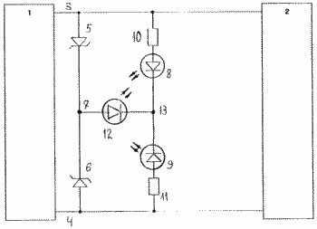
A device for protecting electronic device (RP) from short-term surges in the AC power supply, comprising two voltage limiter (OH) (5, 6) connected in series and in opposition to each other and connected between the conductors, which receives the supply voltage to the (RP ). The apparatus is characterized in that the first resistor (R) (10) and the first light emitting diode (LED) (8) connected in series and form a first chain, the second R (11) and the LED (9) - forming the second chain, the two chains are connected in series and connected to the conductors, which receives a voltage to the RP. The first and second LEDs (8 and 9) included counter. Points chains and OH compounds connected through a third LED (12). If a positive half-cycle of the mains voltage ON (5) conducts, OH (6) - closed, SD (12) - Lights, LED (9) is not lit, even through him as through a diode in reverse polarity will be current limited high-resistance F (11). At short-term surges - only LED lights (12). If the damage threshold is exceeded, OH (5) or (6) - lights or LED (8) or LED (9). If two LEDs are lit (8 and 9), and LED (12) is not lit, then two out of order OH (5 and 6). EFFECT: The device enables the output display of the system OH (5, 6), which increases the reliability of RP operation. Furthermore, the device indicates the presence or absence of the mains voltage.
DESCRIPTION OF THE INVENTION
The present invention relates to electrical engineering, in particular to devices radioelektronnnyh protection devices, connected to AC power.
It is known that the AC voltage 220 (127) having high-frequency current surge of up to 500 or more, are possible short pulses with an amplitude of more than 1 kV. These voltage spikes passing through the power supply may damage the semiconductor devices and chips or cause malfunctions of electronic devices.
To prevent overvoltage apply special schemes with gas arresters, varistors, zener diodes. But all of these devices have a large transconductance capacitance limits their use at high frequencies (VA Kolosov. Power stationary electronic equipment. M .: Radio and Communications, 1992, p. 111).
Therefore, for the protection of electronic equipment from high voltage surges in the power supply using voltage limiters (suppressor diodes), which have high-frequency properties, Voltage limiters make their way in the case of the voltage applied to them, in excess of the value of breakdown voltage. The device for protection of electronic devices against surges in the power supply using a voltage limiter (prototype), described, for example, in the "Electronic devices for the protection of electronics against electrical overloads" (authors V.P.Cherepanov, A.K.Hrulev and I.P . Bludov. M .: Radio and Communications, 1994, p. 42, Fig. 10.6).
electronic device protection device against transient surges in the AC has two connected in series and counter voltage limiter to each other and connected between the conductors on which the instrument receives the supply voltage. When the network surge voltage limiters one is conducting, the other short breaks, with the overvoltage pulse is limited and does not cause interference or malfunction in radio device. Two oppositely connected in series and the voltage limiter with each other, may be formed as a single device - the symmetrical voltage limiter, with the further connection point is output limiters.
However, in case of failure of one of the voltage limiter (open it, for example, a short-circuit due to a large current) power to the unit will not be broken, but the device will be deprived of surge protection. A fault in the protection device, thus can not be detected immediately, and therefore, is not eliminated. This reduces the reliability of electronic equipment.
The proposed invention solves the technical problem of increasing the reliability of electronic equipment. In addition, it provided more favorable conditions for the operation of electronic equipment by reducing interference.
The essence of the claimed invention is that the electronic device protection device comprises two voltage limiter connected in series and counter connected to each other and between the conductors, which receives a supply voltage to the radio-electronic device (followed features). The apparatus comprises a first and second and third LEDs, and first and second resistors, a first resistor and a first LED connected in series to form a chain of the first LED, a second LED and a second resistor connected in series to form a second LED string. And both LED chains are connected in series and connected to the conductors, which receives a voltage to the radio-electronic devices. LED chains connected to each other so that the first and second LEDs included in opposition to each other, and a connection point with the LED chains connected to the connection point through the third voltage limiters LED. Polarity terminals of the first and second LEDs that are connected via a third LED to the junction of voltage limiters, similar polarities interconnected pins voltage limiters and the polarity of the third LED output connected to the first and second LEDs is similar polarities interconnected terminals of the first and second LEDs.
The proposed electronic device protection device against transient surges in the AC power illustrated by a drawing.
 |
The list of designations in the drawing:
|
The drawing shows a device for protection of electronic device 2 against transient surges in the network 1 AC power supply. Voltage AC mains power supplied through conductors 3 and 4. Voltage limiters 5 and 6 are connected in series and in opposition to each other and at 7 they are connected. They are connected between the conductors 3 and 4, which receives the supply voltage to the radio-electronic devices 2.
Protection device electronic device comprises a first and a second LED 8 LED 9, the first resistor 10 and second resistor 11. The first resistor 10 and the first light-emitting diode 8 connected in series to form a first LED string. A second resistor 11 and the second light-emitting diode 9 connected in series and form a second LED string. Both LED chains connected in series at point 13 and connected to the conductors 3 and 4. The first and second LED chains are connected so that the first 8 and second 9 LEDs included oppositely to each other, and a connection point 13 of LED chains connected to connection point 7 through voltage limiters third LED 12. The polarity connected to point 13 conclusions LEDs 8 and 9 are similar to the polar compound at 7 outputs voltage limiter 5 and 6. The polarity of the output of the third LED 12 connected to the connection point of the LED strings 13 similar polarities conclusions LEDs 8 and 9 are connected connection point 13 to LED chains.
Operation of the device is described below.
Power supply AC mains 1 fed through conductors 3 and 4 to the radio-electronic instruments 2. During normal operation, the AC power supply voltage in the positive half cycle of the network (on the top wire 3 - plus), the upper voltage limiter 5, included in the half-life in the literal direction, conducts a current from the second voltage limiters 6 (bottom) included counter top is closed. The current flowing through the upper voltage limiter 5 passes through the third LED 12 and a second (lower) LED string with the second LED 9 and the second resistor 11 (through the second LED 9, the current flows in spite of the fact that the LED 9 is turned on in reverse polarity; this current limited high-resistance resistor 11 and the reverse voltage across the LED 9 is determined by the negative branch of the current-voltage characteristics of the LED). At the same time the third LED 12 will light up, and the second LED 9 will light (direct current third LED 12 is sufficient for its glow, the reverse current of the LED 9 does not cause the LED illumination 9). There will be no light, and the LED 8, since both ends of the first LED chains are under almost the same potential (voltage drop across the restrictor 5 and the LED 12 are small).
During the negative half cycle of the mains voltage (on the top wire 3 - minus) conducts the second (lower) voltage limiter 6. When this current passes through the third LED 12 and the first (upper) LED chain - the first LED 8 and the first resistor 10. The third LED 12 again emits light, the first LED 8 does not light, the second LED lights and 9 (work protection device similar to that described for the positive half cycle).
At short-term overvoltage in AC power exceeding the permissible reverse voltage surge suppressors 5 and 6, one of them is included in the forward direction, conducting, and the second included the counter first, short breaks and thereby limits the over-voltage pulse in the network and protects apparatus. If the power of the overvoltage does not exceed the threshold voltage limiter power failure, the device then continues normal operation. For short pulse voltage, which does not destroy the voltage limiters, the user nothing changes, the LEDs 8 and 9 are off, and the LED 12 remains lit.
If the power exceeds the overvoltage breakdown threshold voltage limiter 5 or 6, one of the voltage limiter fails (burns).
Let burn voltage limiter 5. This current flows through the voltage limiter 5. When a positive voltage on the wire 3, the current goes through the first resistor 10, the first LED 8 (forward), the second LED 9 (in the opposite direction) and a second resistor 11. The first LED 8 lights up (developed enough for this current is a result of about half the supply voltage), the second light-emitting diode 9 is not lit (reverse current does not cause the LED glow), and the third LED slightly reduces the effect of light, as is now the current passes through it only on the negative half-cycle of mains voltage through a voltage limiter 6. Thus, the glow of the first LED 8 indicates the failure of the first voltage limiter 5.
Similarly, the second LED illumination 9 shows the failure of the second voltage limiter 6. If both LEDs 8 and 9, and the LED 12 is not lit, then went down the two voltage limiter. If not lit, none of the LEDs, there is no voltage on the wires 3 and 4.
If one third LED lights 12, there is a power supply voltage and stops working properly and the electronic device protection device properly.
This indication of the protection device electronic device from the surge in the power supply AC allows the user to be sure of the real-time protection of your device, and take immediate steps to replace a failed protective devices.
From the viewpoint of industrial feasibility of the device, it may be manufactured using common components. It does not require the development and production of special electronic components. If necessary, the manufacture of the device lends itself to automation.
Structurally, it is advisable to place the unit in a small sealed enclosure, followed by pouring of radioactive elements, the housing has a protruding part of the luminous LEDs and two outputs for connection to the network.
This indication of the protection device electronic device from the surge in the power supply AC allows the user to be sure of the real-time protection of your device, and take immediate steps to replace a failed protective devices. Furthermore, due to the first and second high-resistance resistors electronic device protection device selects from the power supply a small current, which reduces the power dissipated by the device and allows to reduce the dimensions of protection device.
CLAIM
protection device electronic device comprising two voltage limiter connected in series and in opposition to each other and connected between the conductors, which receives the supply voltage to the radio-electronic devices, one of which is for short overvoltage in AC power short breaks and thereby limits the over-voltage pulse in network and protects the radio-electronic device, characterized in that it comprises first, second and third LED, the first and second resistors, a first resistor and a first LED connected in series and form a first LED string, the second resistor and a second LED connected in series and form a second LED string , both LED chains connected in series and are connected to the conductors, which receives the voltage to the radio-electronic device, with the LED chains connected to each other so that the first and second LEDs included in opposition to each other, and a connection point LED chains connected to the connection point of the voltage limiters via a third LED, the polarity terminals of the first and second LEDs that are connected via a third LED to the junction of voltage limiters, similar polarities interconnected pins voltage limiters and the polarity of the third LED output connected to the first and second LEDs is similar polarities interconnected terminals first and second LEDs.
print version
Publication date 12.11.2006gg
![]()

Comments
Commenting, keep in mind that the content and the tone of your messages can hurt the feelings of real people, show respect and tolerance to his interlocutors, even if you do not share their opinion, your behavior in terms of freedom of speech and anonymity offered by the Internet, is changing not only virtual, but real world. All comments are hidden from the index, spam control.