| Start of section
Production, amateur Radio amateurs Aircraft model, rocket-model Useful, entertaining |
Stealth Master
Electronics Physics Technologies Inventions |
Secrets of the cosmos
Secrets of the Earth Secrets of the Ocean Tricks Map of section |
  |
| Use of the site materials is allowed subject to the link (for websites - hyperlinks) | |||
Navigation: => |
Home / Technology market / Current inventions and models / Back / |
|
INVENTION
Patent of the Russian Federation RU2155890
DEVICE FOR DISPOSING OF BRAKE ENERGY
![]()
Name of applicant: Vakhrushev Alexander Anatolievich
The name of the inventor: Vakhrushev Alexander Anatolievich
The name of the patent holder: Vakhrushev Alexander Anatolievich
Address for correspondence: 443045, Samara, ul. Aurora 122, ap. 333, Sinitsyna LI
Date of commencement of the patent: 1999.12.07
The invention relates to mechanical engineering and can be used in mechanisms operating with frequent stops and intense dispersals, for example for cars mainly in urban conditions. The braking energy recycling device contains a hydraulic cylinder with a rod, a pump and an oil tank. To the hydraulic cylinder, from the side of the stem, an additional housing is coaxially connected with a spring located in it and supported on the rod of the hydraulic cylinder. Inside the coil is also aligned coaxially with the possibility of reciprocating the protruding part of the rod rigidly connected to the rack that projects out of the housing with which the power take-off pin periodically engages. The cavity of the hydraulic cylinder is connected through a non-return valve to the oil tank pump connected to the brake actuator and the pressure relief valve connected to the speed-on drive. The technical result consists in creating from the known units a compact device for saving any kind of fuel or energy by recuperating the braking energy suitable for recoil during acceleration and / or starting the engine.
DESCRIPTION OF THE INVENTION
The invention relates to mechanical engineering and can be used in mechanisms operating with frequent stops and intense dispersals, for example for cars mainly in urban conditions.
Recuperative braking is known, in which the mechanical energy supplied to the shaft is converted into electric energy and returned to the supply network [1].
There are recuperative brakes used in engineering, containing a battery of energy in the form flywheels [2], screw [3] or flat spiral springs [4].
The closest to the technical essence of the information sources available to the applicant is the device according to pat. RF N 2017024, F 16 D 61/00 of 10.06.91, publ. July 30, 1994, bul. N 14, a recuperative brake comprising a helical spring disposed on the stem between the movable disc and the piston of the annular cylinder, which in turn is connected to a hydraulic pump. Hydraulic cylinder serves to control the intensity of deceleration (acceleration) during the process of deceleration (acceleration) by the commands of the control unit.
This device is used as a brake, combined with an energy storage.
The object of the invention is to create from the known units a small-sized, easy-to-use device for saving any kind of fuel or energy consumed by the vehicle while driving, by recuperating the braking energy suitable for recoil, not only during acceleration, but also when starting the engine in the parking lot.
The stated task is solved by the fact that the braking energy utilization device comprises a hydraulic cylinder, a pump and an oil tank. And to the hydraulic cylinder from the side of the stem is coaxially attached an additional body with a spring placed in it and supported on the rod of the hydraulic cylinder. Inside the spring and coaxially arranged to reciprocate the protruding part of the rod, rigidly connected to the rack protruding beyond the frame. With it, the power take-off gear periodically engages. The cavity of the hydraulic cylinder is connected through a check valve to the oil tank pump. The pump is connected to the brake actuator, and the pressure relief valve is connected to the speed-sensing drive.
The figure shows a device showing a power take-off pin 1, a rack 2, a spring 3, a housing 4, a hydraulic cylinder 5, a rod 6, a piston 7, a pressure collection valve 8, a check valve 9, an oil pump 10, an oil tank 11, a drive Brakes 12, speed drive 13.
The device comprises a hydraulic cylinder 5 and a housing 4 coaxially connected thereto. A spring 3 is supported in the housing 4, in which a protruding part of the rod 6 of the hydraulic cylinder 5, which is rigidly connected to the protruding body, is also coaxially disposed in a reciprocating manner 4 toothed rack 2. To rail 2, under the influence of the speed drive 13, the power take-off pin 1 is connected or disconnected from it. The cavity of the hydraulic cylinder 5 through the check valve 9 is connected to the pump 10 of the oil tank 11. The pump 10 is connected to the brake actuator 12. The pressure relief valve 8 is connected to the speed-on drive 13.
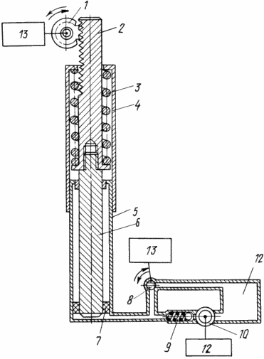 |
The device works as follows. The oil pump 10, when the drive of the vehicle brake 12 is turned on, supplies oil from the oil tank 11 through the check valve 9 to the cavity of the hydraulic cylinder 5. The pressure relief valve 8 is closed, the power take-off pin 1 is withdrawn from the rack bar 2. The piston 7, pushing the rod 6 With the rack 2 mounted on it, compresses the spring 3, utilizing the braking energy. Under the influence of the speed drive 13, the power take-off 1 is fed to the rack 2 before engaging it. The pressure relief valve 8 opens. The oil from the cavity of the hydraulic cylinder 5 is discharged into the oil tank 11. The spring 3, releasing, moves the pressure-released rod 6 with the rack 2 located on it and transmits the energy accumulated during braking to accelerate the car or, Start the engine in the parking lot. The spring 3 is opened until the next activation of the brake actuator 12, and then starts to compress again, summing up the remaining unused energy during the next acceleration and the new energy supply. To accumulate the utilized energy of braking, it is sufficient to accelerate the car several times before stopping the car and stop braking. This creates an energy reserve in the spring 3 supported by the rod 6 of the hydraulic cylinder 5. With complete compression of the spring, the oil pump 10 is automatically shut off (not shown). Pressure relief in the cylinder cavity is prevented by the check valve 9 and the closed pressure relief valve 8. When starting the engine, it is sufficient to open the pressure relief valve 8 and to engage the power take-off pin 1 with the rack 2. The device then operates in the same way as during acceleration. |
The use of known units - springs and hydraulic cylinders with a pump and a tank with a new set of characteristics expressed in the formula, makes it possible to create an easy-to-use device available for manufacturing even to a small enterprise.
When coaxial placement on the hydraulic cylinder of an additional housing with a spring located in it and supported by a spring in the cylinder, inside which the projecting part of the rod rigidly connected with the rack protruding beyond the housing from which it periodically enters into The gearing of the power take-off gear, and the placement of a non-return valve between the cavity of the hydraulic cylinder and the oil tank pump, and the pressure relief valve between the cavity and the tank itself allows the accumulated energy of the braking to be summed up, the efficiency of utilization and the expenditure of it to accelerate or start the engine through the power take-off gear.
INFORMATION SOURCES
Polytechnical dictionary. M., "The Soviet Encyclopedia", 1980, p. 448.
AS N 1474355, F 16 D 61/00, dated 27.07.87, publ. 23.04.89, bul. N 15.
A. with N 1216471, F 16 D 61/00, dated May 30, 1984, publ. 07.03.86, bul. N 9.
A. with N 1395863, F 16 D 61/00, dated 06.08.85, publ. 15.05.88, bul. N 18.
CLAIM
A braking energy utilization device comprising a hydraulic cylinder, a pump and an oil tank, characterized in that an additional housing is coaxially connected to the hydraulic cylinder on the stem side, with a spring located therein and supported on the rod of the hydraulic cylinder, in which it is coaxially arranged to reciprocate The protruding part of the rod rigidly connected to the rack which is projected beyond the housing with which the power take-off pin periodically engages, the cavity of the hydraulic cylinder is connected through a check valve to the oil tank pump connected to the brake actuator and the pressure relief valve connected to the speed-on drive.
print version
Date of publication 30.12.2006гг
![]()

Comments
When commenting on, remember that the content and tone of your message can hurt the feelings of real people, show respect and tolerance to your interlocutors even if you do not share their opinion, your behavior in the conditions of freedom of expression and anonymity provided by the Internet, changes Not only virtual, but also the real world. All comments are hidden from the index, spam is controlled.