
| Start of section
Production, amateur Radio amateurs Aircraft model, rocket-model Useful, entertaining |
Stealth Master
Electronics Physics Technologies Inventions |
Secrets of the cosmos
Secrets of the Earth Secrets of the Ocean Tricks Map of section |
  |
| Use of the site materials is allowed subject to the link (for websites - hyperlinks) | |||
Navigation: => |
Home / Technology market / Current inventions and models / Back / |
|
INVENTION
Patent of the Russian Federation RU2187655
PISTON MACHINE
![]()
Applicant's name: Muradyan Levon Muradovich (AM); Muradyan Murad Levonovich (AM); Sedrakyan Zh.L. (RU)
The name of the inventor: Muradyan Levon Muradovich (AM); Muradyan Murad Levonovich (AM); Sedrakyan Zh.L. (RU)
The name of the patent holder: Muradyan Levon Muradovich (AM)
Address for correspondence: 115446, Moscow, ul. Academician Millionshchikov, 18, ap. 322. Z.L. Sedrakyan
The effective date of the patent: 2001.06.08
The machine is designed to convert the energy of the working fluid (gas, vapor, liquid) into mechanical work or vice versa. The machine comprises a body 3, at least one prismatic spring 1, a lid 4 provided with valves 5 and 10, an elastic prismatic cylinder 2, a piston 6 with a connecting rod 11 connected to a guide support 7. The piston 6 is coaxially fixed to the end face of the prismatic spring 1, In which an elastic prismatic cylinder 2 is installed, the open end of which, together with the other end of the prismatic spring 1, is hermetically fixed to the body 3 by means of the lid 4, and the bottom of the elastic prismatic cylinder 2 is hermetically fixed to the piston 6. The guide support 7 kinematically connected to the connecting rod 11, provides non-contact movement of the piston 6 along the geometric axis of the prismatic spring 1. The invention provides an increase in the reliability and durability of the machine, simplifying the operating conditions.
DESCRIPTION OF THE INVENTION
The invention relates to power engineering, namely to machines for converting the energy of a working fluid (gas, vapor, liquid) into mechanical work and vice versa, and more particularly to piston machines.
To convert the energy of the working fluid (gas, steam or liquid) into mechanical work, for example reciprocating piston, or vice versa, piston machines such as hydraulic cylinders, reciprocating engines, compressors, pumps, etc. are widely used.
The closest to the invention is a piston machine comprising a body with at least one end cap, a spring arranged in the housing at least one spring coaxially mounted in the elastic cylinder, the ends of which are fixed at the ends of the spring, the valves installed in the cover, the piston with the rod And guide support (US 5158005 A, cl. F 01 B 19/00, published on October 27, 1992) .
Disadvantages of this invention are the friction occurring between both telescopic cylinders and between the inner cylinder and the flexible elastic balloon, which leads to a rapid wear of these parts; Limited travel of the movable telescopic cylinder and the need for high-precision machining of the mutually contacting surfaces of the cylinders.
The object of the invention is to eliminate the above-mentioned drawbacks and to provide increased reliability and durability of the machine, simplifying the operating conditions thereof.
This object is achieved due to the fact that in a piston machine comprising a casing with at least one end cover, at least one spring located in the casing, coaxially arranged in the elastic balloon, the ends of which are fixed at the ends of the spring, the valves installed in the lid , A piston with a rod and a guide support, one end of the spring by means of a lid is hermetically fixed to the body, another piston with a stem is attached coaxially with it to form a sealed chamber with the possibility of converting the energy of the working medium into a piston motion along the geometric axis of the spring. Moreover, the spring and the cylinder can have a prismatic shape, a cylindrical shape or a truncated cone shape. The spring and the balloon can be in the form of a toroidal part, and the piston can be mounted to be movable along the geometric axis of the spring by means of a rotational guide. And the spring can be made compound. The elastic balloon can be made in the form of a bellows, and the inner surface of the spring to be able to cover it during deformation.
In an embodiment, an additional elastic balloon is provided in which a spring is mounted together with an inner elastic balloon to form a sealed chamber with the possibility of supplying a cooling and lubricating fluid to this chamber.
The intermediate zone between the housing and the spring can be filled with a cooling and lubricating fluid.
The embodiment provides for the use of a piston motion actuator, wherein the valves are arranged to control the pressure of the working fluid.
The balloon can be made of an elastic material and reinforced with helical-shaped strings, for example a cord, relatively to the cylinder axis.
According to yet another embodiment, the lid is in the form of a cup located in the housing, and a spring with a balloon is located between the outer surface of the lid and the inner surface of the housing. The cylinder can be installed in a spring and fixed in a prestressed state.
The spring is the main part of the proposed piston machine. It serves both to perceive the pressure of the working fluid and to ensure uniform elongation and shortening of the elastic balloon, and to create a working force that ensures the displacement of the piston when the machine is operating in the engine or hydraulic cylinder mode. The spring stiffness should be selected in such a way as to ensure the strength of the pressure chamber with maximum displacement of the piston. The proposed machine allows the use of the potential energy of spring elastic deformation to ensure the piston's back stroke.
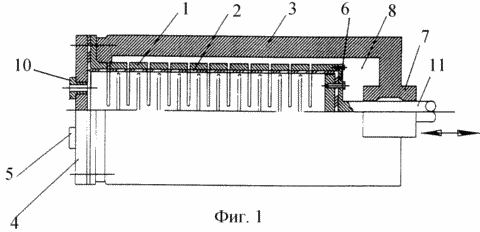
For powerful piston machines in which high-pressure working bodies are used or a large pressure force is to be obtained, preference should be given to prismatic prism springs (FIG. 1, FIG. 2).
For machines operating in the compressor mode, it is preferable to use prismatic springs (Fig. 3) whose polygonal flat elements work on joint bending and torsion, however, unlike slotted springs, they are assembled from separate flat elements, the distance between which is set during the assembly of the spring With the help of plug-in pads. They allow not only to provide practically any spring rigidity with sufficient strength, but also provide different axisymmetric configurations of the inner surface of the spring, which is very important when using reinforced high-strength threads (cord) or metal, flexible cylindrical cylinders (bellows). The use of an elastic balloon in the piston machine ensures maximum tightness of the pressure chamber without the need for using a forced lubrication system of rubbing surfaces and without high-precision surface treatment of individual machine parts. The elastic balloon is made of an elastic, easily deformable material, for example rubber, and can be in the form of a glass or a pipe. The principle of the piston machine allows the use of materials with low strength characteristics, since the walls of the elastic cylinder are an intermediate link for transferring high pressure of the working fluid to the walls of the prismatic spring, which contributes to the occurrence of relatively low stresses in the walls of the elastic balloon. For this purpose, the thickness of the walls of the flexible balloon is chosen so that, with the maximum stroke of the piston, it is of the same order of magnitude as the distance between the turns of the helical spring or the ring elements of the slotted spring at their maximum open position. For piston machines operating in the compressor mode, the thickness of the walls of the elastic balloon should be taken to be approximately half the distance between the spring ring elements when it is maximally opened, since from this moment the radial deformation of the elastic balloon becomes significant and can lead to the destruction of the balloon. In the machine of the present invention, both ends of the spring and the elastic balloon are fixed together in such a way that they create conditions for their joint deformation and thus allow in the contact zone of the elastic ballon with the inner cavity of the spring to practically eliminate their mutual displacements. This allows you to reduce wear and significantly increase the durability of the elastic balloon. The pressure chamber lid, equipped with valves to allow the inlet and outlet of the working fluid, hermetically closes the open end of the elastic balloon and, together with the spring, attaches it to the body of the machine. In the body of the machine there is a cavity in which a spring with an elastic balloon is installed with a gap. The piston and connecting rod are made as one piece and coaxially fixed on the movable end of the spring. They are attached to the bottom of the elastic balloon. The guide support is fixed to the body of the machine and ensures the movement of the piston along the geometric axis of the spring.
The use of a prestressed composite prismatic spring allows the strength of the pressure chamber to be substantially increased at a constant spring rigidity. The installation of a helical spring, between which there is no gap at the initial moment, with the necessary stiffness inside the slotted spring, allows a minimum size of the inter-turn distance with the maximum stroke of the piston, and thereby significantly reduce the operating stresses acting in the walls of the elastic balloon by increasing the number of turns at the length of the spring. This makes it possible to reduce the requirements for the strength characteristics of elastic cylinders.
To increase the elastic elasticity of the elastic balloon, to reduce the amount of force necessary to achieve the maximum stroke of the piston, ensuring uniform packing of the elastic balloon during the reverse deformation of the spring, it is convenient to use an elastic balloon having the shape of a bellows, whose step is equal to the step of the spring in an undeformed state. This design allows not only to significantly increase the maximum stroke of the piston and the durability of the elastic balloon, but also to use metal cylindrical cylinders having the shape of a bellows. This makes it possible to use the piston machine under severe operating conditions when high temperatures or high dynamic pressures act on the elastic cylinder or it works in corrosive environments where it is practically impossible to use elastic cylinders made of organic materials.
To reduce the friction and wear of the elastic balloon, and also to cool the movable links of the piston machine, a lubricating liquid is supplied into the area between the elastic balloon and the walls of the machine body. You can make a screw groove on the inner surface of the spring to improve the lubrication process of the flexible balloon. This allows to increase the durability of the main parts of the piston machine and creates the conditions for its use in intensive operation modes.
To avoid the use of seals in the lubrication-cooling system, it is preferable to use a second elastic cylinder with a spring installed in it and another elastic balloon. In this case, the ends of the outer cylinder are tightly fixed to the ends of the prismatic spring, forming, together with the internal elastic cylinder, a closed chamber into which a cooling lubricating liquid is supplied. This avoids the loss of cooling lubricating fluid and provides a reliable cooling system.
It is possible to apply an antifriction coating on the inner surface of the spring, for example graphite. This makes it possible to substantially reduce frictional forces between the spring and the elastic balloon and thereby increase the durability of the elastic balloon. In order to increase the contact strength of the latter, it can be reinforced with strong threads (cord) helically shaped with respect to the longitudinal axis of the balloon, this arrangement of the reinforcement makes it possible to provide a comparatively high strength of the elastic balloon with sufficient elasticity, which creates conditions for the use of high-pressure working bodies.
To reduce the touch of the walls of the elastic cylinder with the walls of the spring, it is convenient to make an elastic balloon in the form of a truncated cone, the vertex of which is on the piston side. This will reduce the frictional forces in the area of the largest movement of the elastic balloon and increase its longevity.
To obtain a high compression ratio of the working fluid in the pressure chamber, it is convenient to make the cylinder cover in the form of a cup (FIG. 3), whose length is equal to the working length of the spring in its undeformed state, and the outside diameter of the glass is smaller than the diameter of the cylinder inscribed in the spring cavity, An intermediate zone formed between the outer surface of the lid and the spring cavity, install an elastic balloon.
The reciprocating machine can be made with an elastic balloon of a tubular shape. Then the movable end of the elastic balloon must have a flange which, by means of a piston, is sealed to the movable end of the spring (FIG. 3).
To increase the durability of an elastic balloon made from certain rubber grades, for example from isoprene rubber, an elastic balloon must be fixed in a spring in a prestressed state. The same applies to cylinders having the shape of bellows.
The presence of valves allows the piston machine of the proposed design to be used in the pump or compressor mode.
The described improvements make it possible to reduce the accuracy of manufacturing parts and thereby significantly reduce the laboriousness of production, ensure high tightness of the pressure chamber, improve the lubrication conditions of the mutually moving surfaces of machine parts, enable the movement of the piston along the arc of the circle and facilitate the maintenance of the machine. Simultaneously, the manufacture of high-capacity machines is much simpler, and the repair of the machine, which reduces to the replacement of an elastic balloon, is simplified.
The invention is explained in the drawings, wherein
1 schematically shows a piston machine, a general view
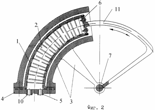
FIG. 2 shows an embodiment of a reciprocating machine with a cylinder having the shape of a severed torus
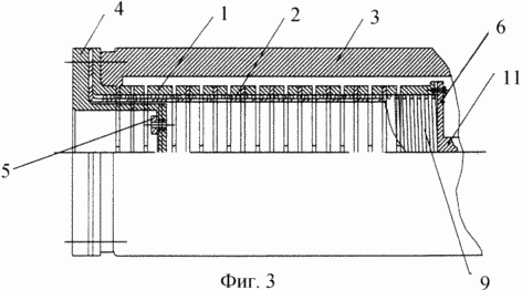
FIG. 3 - piston machine with two springs (slotted and screw) and a lid shaped like a glass
The piston machine comprises at least one spring 1 (prismatic, cylindrical, conical, toroidal, etc.), one end of which has a flange allowing it to be bolted to the body 3 and hermetically sealed with a cover 4 with an inlet 5 installed thereon and Outlet valve. In the cavity of the spring 1, an elastic balloon 2 having the shape of a cup is installed coaxially, the open end of which is sealed together with the spring 1 by means of a lid 4 on the casing 3. The bottom of the elastic balloon 2 and the movable end of the spring 1 are fixed to the piston 6 tightly and without creating initial stresses In the spring 1 and in the elastic cylinder 2. The piston 6 with the connecting rod 11 is mounted movably and is connected to a guide support 7 which is fixedly fixed to the body 3 of the piston machine. Housing 3 with a spring 1 form a cavity 8, allowing easy cooling and lubrication of the spring 1 and the elastic balloon 2.
2 shows an embodiment of a piston machine when the spring 1 and the elastic balloon 2 are in the form of a cut torus, and the guide support 7 is an element of the rotating pair.
The reciprocating machine in the engine mode works as follows. Through the inlet valve 5, a working fluid is supplied under pressure into the flexible balloon 2. The elastic balloon 2, expanding, creates a motor force on the movable end of the spring 1, which deforms the piston 6 fixed to them. The piston 6 moves along the arc along the geometric axis of the spring 1. When the piston 6 is reversed, the exhaust valve 10 opens and The elastic force acting on the side of the elastic balloon 2 and the spring 1, returns the piston 6 to its initial position. In this case, the working fluid is expelled from the balloon 2 through the exhaust valve 10 (FIG. 2).
In Fig. 3 schematically shows a piston machine with a lid 4 having a cup shape. The spring 1 is integral and includes one slotted spring and one screw spring 9, and the minimum size of the pressure chamber is determined by the product of the length of the lid-cup 4 by the cross-sectional area formed between the outer surface of the lid-cup 4 and the inner surface of the deformed elastic balloon.
When using a piston machine in the compressor or pump mode, the operation is carried out in the reverse order using a drive (not shown in the drawings), which ensures the movement of the piston and the connecting rod and the compression of the cylinder and spring.
The present invention can be used in devices for converting the energy of a compressed working medium into mechanical work and vice versa in order to convert the mechanical work performed by the machine to the energy of a compressed working fluid.
CLAIM
A piston machine comprising a casing with at least one end cap housed in a casing, at least one spring coaxially mounted therein an elastic cylinder, the ends of which are fixed to the ends of the spring, the valves installed in the lid, the piston with the stem and The guide support, characterized in that one end of the spring is sealed by a cover on the body, a piston with a rod is attached coaxially to it at the other end of the spring to form a sealed chamber with the possibility of converting the energy of the working fluid into a piston motion along the geometric axis of the spring.
The machine according to claim 1, characterized in that the spring and the cylinder have a prismatic shape.
The machine according to claim 1, characterized in that the spring and the cylinder are cylindrical.
The machine according to claim 1, characterized in that the spring and the balloon are in the form of a truncated cone.
The machine as claimed in claim 1, characterized in that the spring and the balloon are in the form of a toroidal part, and the piston is movable along the geometric axis of the spring by means of a rotational guide.
A machine according to any one of claims 1 to 5, characterized in that the spring is made integral.
The machine according to any one of claims 1 to 6, characterized in that the elastic container is made in the form of a bellows, and the inner surface of the spring is designed to fit around it during deformation.
A machine according to any one of claims 1 to 7, characterized in that the intermediate zone between the body and the spring is filled with a cooling and lubricating fluid.
A machine according to any one of claims 1 to 8, characterized in that it is provided with a drive for driving the piston, and the valves are arranged to control the pressure of the working fluid.
The machine according to any one of claims 1 to 9, characterized in that the balloon is made of an elastic material and is reinforced by helically threaded yarns, for example a cord, arranged with respect to the cylinder axis.
The machine according to any one of claims 1 to 10, characterized in that the lid is in the form of a cup located in the casing, and a spring with a canister is disposed between the outer surface of the lid and the inner surface of the casing.
The machine according to any one of claims 1 to 11, characterized in that the balloon is installed in a spring and fixed in a prestressed state.
The machine as claimed in any one of claims 1 to 12, characterized in that it is provided with an additional elastic balloon in which a spring is installed together with an inner elastic balloon to form a sealed chamber with the possibility of supplying a cooling and lubricating liquid to this chamber.
print version
Date of publication 28.12.2006гг
![]()

Comments
When commenting on, remember that the content and tone of your message can hurt the feelings of real people, show respect and tolerance to your interlocutors even if you do not share their opinion, your behavior in the conditions of freedom of expression and anonymity provided by the Internet, changes Not only virtual, but also the real world. All comments are hidden from the index, spam is controlled.