
| Start of section
Production, amateur Radio amateurs Aircraft model, rocket-model Useful, entertaining |
Stealth Master
Electronics Physics Technologies Inventions |
Secrets of the cosmos
Secrets of the Earth Secrets of the Ocean Tricks Map of section |
  |
| Use of the site materials is allowed subject to the link (for websites - hyperlinks) | |||
Navigation: => |
Home / Technology market / Current inventions and models / Back / |
|
INVENTION
Patent of the Russian Federation RU2187656
ROTARY-PLATE MACHINE
![]()
Name of applicant: Pchelnikov Ilya Vladimirovich
The name of the inventor: Zalygin Yu.R.
The name of the patent owner: Pchelnikov Ilya Vladimirovich
Address for correspondence: 127562, Moscow, PO Box 55, VVShtyolkov
The effective date of the patent: 2001.03.12
The invention relates to the field of power engineering and can be used in pneumatic and hydraulic machines of volumetric action. The rotary-lamellar machine has a cylindrical body with an internal cylindrical bore. The hollow cylindrical rotor is eccentrically placed in the boring of the housing and has longitudinal radial profiled grooves. Separating plates with eyelets are installed in liners having a plano-convex shape. The inserts are placed in the rotor with the possibility of turning in grooves. Each of the inserts of the plate is made in the form of a plano-convex structural element with a different radius of curvature of the outer convex surface along its length and has a central and peripheral portions. The inserts are fixed to each other by at least two hollow damping sleeves. Sleeves are installed on the peripheral sections of the liners. At least the working surfaces of the plate, the outer surfaces of the bushings and the central portions of the liners interacting with the working surfaces of the plate are made with a ceramic coating. Reduces friction in the working surfaces, prevents jamming of interacting elements.
DESCRIPTION OF THE INVENTION
The invention relates to the field of power engineering and can be used in the construction of pneumatic and hydraulic volumetric machines operating both in the engine mode and in the pump mode.
From the state of the art, a rotary lamellar machine is known comprising a fixed body with an internal cylindrical bore and supply and discharge ports, respectively connected with the pressure and discharge lines, a hollow cylindrical rotor with a drive and longitudinal radial profiled grooves with opposite concave arcuate surfaces Eccentrically placed in the bore of the body, installed in the liners, spacer plates with lugs embracing an axis coinciding with the boring axis of the housing, the inserts being rotatably disposed in the radial grooves of the rotor (see U.S. Patent 3,892,502, NCI 418/15, 1975 ) .
The achievement of the required technical result in the known rotary-lamellar machine is prevented by significant mechanical losses during the motion of the separation plates in the radial grooves of the cylindrical rotor, and the phenomenon of wedging of the inserts and spacer plates, which takes place at high friction coefficients. This is observed as a result of the deviation of the profile of the liner surface interacting with the surface of the rotor groove, which can occur either as a result of technological errors in the manufacture, or as a result of the surfacing of the surfaces with each other.
The task, to solve which the claimed invention is directed, is the creation of a rotary-lamellar machine providing a qualitative improvement in performance characteristics and an increase in the life of a rotor-plate machine.
The technical results obtained from the implementation of the claimed invention include reduction of friction in working friction surfaces, prevention of jamming of interacting elements and, as a result, reduction of total mechanical losses in the rotor-plate machine.
The object is achieved, and the technical result is achieved in that, in a rotor-plate machine comprising a fixed body with an internal cylindrical bore and supply and discharge windows of the working medium connected with the pressure and discharge lines, respectively, a hollow cylindrical rotor with a drive and longitudinal radial profiled Grooves with opposite concave arcuate surfaces, eccentrically placed in the bore of the body, installed in liners having a plano-convex shape, dividing plates with lugs embracing an axis coinciding with the axis of the boring of the body, the inserts being rotatably mounted in the longitudinal radial profiled grooves of the rotor By their external convex surface with their opposite concave arcuate surfaces, according to the invention, each of the inserts of the separation plate is made in the form of a plano-convex structural member with a different radius of curvature of the outer convex surface developed in the direction transverse to the direction of motion of the separation plate, along its length with the central and located along both The working part of the separating plate is placed in the liners within the central region, the liners of each separation plate are arranged to interact with each other by their planes in a plane coinciding with the plane of motion of the separating plate and are fixed to each other by at least two hollow damping sleeves Mounted on the peripheral portions of the liners surrounding them and interacting with their outer surface together with the outer surface of the central portions of the inserts with the concave surfaces of the longitudinal radial profiled grooves of the rotor to form friction pairs with them, the damping sleeves having a cutout for the separating plate eye, At least the working surfaces of the separating plate, the outer surfaces of the damping sleeves and the central portions of the liners and the friction surface of the liners interacting with the working surfaces of the separation plate are provided with a ceramic coating.
In the rotor-plate machine, the peripheral portions of the inserts can be formed with a radius of curvature of the outer convex surface different from the radius of curvature of the outer convex surface of the central portion, and, for example, with an equal curvature radius.
The radius of curvature of the outer surface of the damping sleeves can be made equal to the radius of curvature of the outer surface of the central portion of the corresponding liner.
Each damping sleeve can be provided with a locking projection on the surface of its internal cavity, cooperating with a reciprocating groove formed on the outer convex surface of each peripheral portion of the liner.
The surfaces of the central and peripheral sections of the liners and the outer surfaces of the damping sleeves can be made cylindrical, like their internal surfaces.
The invention is explained in the drawings, wherein
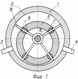 1 shows a rotary plate |
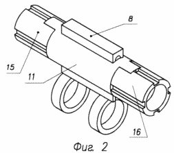 FIG. 2 shows the arrangement of the separating |
 |
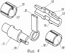 |
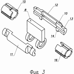
FIG. 3 and 4 are the same as in FIG. 2, only in a detachable state for two examples | |
 FIG. 5 is a view of the damping sleeve from its end |
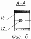 FIG. 6 is a section of AA in FIG. 5 |
The rotary lamellar machine has a cylindrical body 1 with an internal cylindrical bore 2 and a supply port 3 and a working medium outlet 4 communicating with the discharge and drain (not shown) lines. The hollow cylindrical rotor 5 is eccentrically arranged in the bore 2 of the body 1, has a drive (not shown) and longitudinal radial profiled slots 6 with opposite concave arcuate surfaces 7. The separating plates 8 with the eyes 9 surrounding the axis coinciding with the axis (not shown) of the bore 2 Of the housing 1 are installed in the inserts 10 having a plano-convex shape. The inserts 10 are placed in the hollow cylindrical rotor 5 with the ability to rotate in the longitudinal radial profiled grooves 6 due to the interaction of their outer convex surface 11 with opposite concave arcuate surfaces 7.
Each of the inserts 10 of the separating plate 8 is made in the form of a plano-convex structural element developed in a direction transverse to the direction of motion of the separation plate 8, with a different radius of curvature of the outer convex surface 11 along its length. Each liner 10 has a central 12 and peripheral 13 portions.
The inserts 10 of each spacer plate 8 are arranged to interact with each other by their planes 14 in a plane (not shown) coinciding with the plane of movement of the separating plate 8. The inserts 10 are fixed to each other by at least two hollow damping sleeves 15. The sleeves 15 are mounted on the peripheral portions 13 of the inserts 10 cover them and interact with their outer surface 16 together with the outer surface of the central portion 12 of the insert 10, with the concave arcuate surfaces 7 of the longitudinal radial profiled slots 6 of the rotor 5 forming friction pairs with them.
At least the working surfaces of the separating plate 8, the outer surfaces of the damping sleeves 15 and the central portions 12 of the inserts 10 interacting with the working surfaces of the separating plate 8 are provided with a ceramic coating.
Each damping sleeve 15 can have a locking protrusion 17 on the surface 18 of its internal cavity interacting with a reciprocating groove 19 formed on the outer convex surface of each peripheral portion 13 of the insert 10.
ROTARY-PLATE MACHINE WORKS AS FOLLOWING
In the mode of pneumatic or hydraulic motor, the processes occurring with the working body and its interaction with the elements of the rotary-lamellar machine are analogous to the processes occurring in the prototype, i.e. When the rotor 5 is rotated by the drive in the cylindrical bore 2 of the housing 1, a working chamber is formed between the two separation plates 8, increases in volume and, when connected to the pressure line, is filled through the supply port 3 with a working medium - the working medium. When a certain volume is reached in the working chamber, this connection is interrupted by overlapping one of the separation plates 8 of the supply window 3 of the working medium and, consequently, communication with the pressure line. Then, the working medium moves to the drain line and ejects it to the last through the window 4.
The separating plates 8 make alternating movements in the inserts 10 due to the fact that they are installed eccentrically in the bore 2 of the housing 1 through the eyes 9. The inserts 10 themselves are slid by rotational movement in the longitudinal radial profiled grooves 6 due to the interaction of their external convex surface 11 with opposite concave arc- Surfaces 7 of the rotor 5. The hollow damping sleeves 15 are mounted on the peripheral portions 13 of the inserts 10, cover them, fix each other and cooperate with their outer surface 16 together with the outer surface of the central portion 12 of the insert 10, with the concave arcuate surfaces 7 of the longitudinal radial profiled grooves 6 of the rotor 5, forming pairs of friction with them.
The presence of damping sleeves 15 in the structure of the inserts 10 makes it possible to prevent the latter from sticking in the longitudinal radial profiled grooves 6 of the rotor 5.
Due to the fact that at least the working surfaces of the separating plate 8, the outer surfaces of the damping sleeves 15 and the central portions 12 of the inserts 10 interacting with the working surfaces of the separating plate 8 are ceramic-coated, in all pairs of friction of the rotor plate machine, the wear resistance of the friction- Elements, which increases the total resource of the rotary-lamellar machine itself.
The rotary-lamellar machine is made of traditional construction materials and can be manufactured under experimental and / or batch production using traditional technology.
CLAIM
1. A rotary lamellar machine comprising a fixed body with an internal cylindrical bore and a supply and discharge window of the working medium communicating with the pressure and discharge lines, respectively, a hollow cylindrical rotor with a drive and longitudinal radial profiled slots with opposite concave arcuate surfaces eccentrically located in the bore Housings installed in liners having a plano-convex shape, separate plates with lugs embracing an axis coinciding with the boring axis of the housing, the inserts being rotatably mounted in the longitudinal radial profiled grooves of the rotor due to interaction by their outer convex surface with their opposing concave arcuate Surfaces, characterized in that each of the inserts of the separating plate is made in the form of a flatly convex structural element with a different radius of curvature of the external convex surface developed along the lengthwise direction of the movement of the separation plate, with its central length and the central peripheral portions located on both sides, Part of the separation plate is placed in the liners within the central region, the liners of each separation plate are arranged to interact with each other by their planes in a plane coinciding with the plane of movement of the separation plate and are fixed to each other by at least two hollow damping sleeves mounted on the peripheral portions of the inserts Embracing them and interacting with their outer surface together with the outer surface of the central portions of the liners with the concave surfaces of the longitudinal radial profiled grooves of the rotor to form friction pairs with them, the damping sleeves being provided with a notch under the eye of the separating plate, and at least the working surfaces of the separating plate Plates, the outer surfaces of the damping sleeves and the central portions of the liners and friction surfaces of the liners interacting with the working surfaces of the separation plate are provided with a ceramic coating.
2. A rotary lamellar machine according to claim 1, characterized in that the peripheral portions of the inserts are formed with a curvature radius of the outer convex surface different from the radius of curvature of the outer convex surface of the central portion.
3. The rotary plate machine according to claim 1, characterized in that the peripheral portions of the inserts are formed with an equal curvature radius.
4. A rotary lamellar machine according to claim 1, characterized in that the radius of curvature of the outer surface of the damping sleeves is made equal to the radius of curvature of the outer surface of the central portion of the corresponding liner.
5. The rotary plate machine according to claim 1, characterized in that each damping sleeve is provided with a fixing protrusion on the surface of its internal cavity interacting with the reciprocating groove formed on the outer convex surface of each peripheral portion of the insert.
6. The rotary plate machine according to claim 1, characterized in that the surfaces of the central and peripheral portions of the inserts and the outer surfaces of the damping sleeves are cylindrical.
7. A rotary plate machine according to claim 1 or 6, characterized in that the inner surfaces of the damping sleeves are cylindrical.
print version
Date of publication 28.12.2006гг
![]()

Comments
Commenting on, remember that the content and tone of your message can hurt the feelings of real people, show respect and tolerance to your interlocutors even if you do not share their opinion, your behavior in the conditions of freedom of expression and anonymity provided by the Internet, changes Not only virtual, but also the real world. All comments are hidden from the index, spam is controlled.