
Chernobyl: Part 1. Description of the Chernobyl NPP with RBMK-1000 reactors.
Information on the Chernobyl accident and its consequences prepared for the IAEA Report No. 1 (INSAG-1)
C O R E R A N E E
Flash drive
0. Introduction
1. Description of the Chernobyl NPP with RBMK-1000 reactors.
2. Chronology of the development of the accident.
3. Analysis of the process of development of the accident on a mathematical model.
4. Causes of the accident.
5. Preventing the development of an accident and reducing its consequences.
6. Control over radioactive contamination of the environment and public health.
7. Recommendations for improving the safety of nuclear power.
1. DESCRIPTION OF THE CHERNOBYL NPP WITH RBMK-1000 REACTORS
1.1. Project data
1.2. Description of the reactor unit of the fourth block of the Chernobyl NPP
1.3. The main physical characteristics of the reactor
1.4. Security systems
1.5. Description of the site of the Chernobyl nuclear power plant and its location
1.1. Project data
The design capacity of the ChNPP is 6 GW, as of January 1, 1986, the capacity of four nuclear power units is 4 GW.
1.2. Description of the reactor unit of the fourth block of the Chernobyl NPP
The main design features of RBMK reactors are:
- Vertical channels with fuel and heat carrier, allowing local fuel overloading when the reactor is operating;
- fuel in the form of bundles of cylindrical fuel rods made of uranium dioxide in zirconium tube-shells;
- graphite moderator between channels;
- light water boiling coolant in the circuit of multiple forced circulation (CMPC) with direct steam supply to the turbine.
The RBMK-1000 reactor with a thermal capacity of 3200 MW (Figure 1) is equipped with two identical cooling loops; Each loop is connected to 840 parallel vertical channels with TVS. The cooling loop has four parallel main circulation pumps (MCP): three operating, supplying 7,000 t / h of water with a head ~ 1,5 MPa, and one reserve.
The control and protection system (CPS) of the reactor is based on the displacement of 211 solid rods-absorbers in specially allocated channels, which are cooled by water of an autonomous circuit. The system provides: automatic maintenance of a given power level; Rapid power reduction by the rods of automatic regulators (AR) and manual regulators (RR) according to the signals of the failure of the main equipment; Emergency termination of the chain reaction by emergency protection rods (A3) by impulses of dangerous deviations of the unit parameters or equipment failures; Compensation of changes in reactivity during heating and output to power; Regulation of energy release in the core.
RBMK are equipped with a large number of independent regulators, which, when triggered by the A3, are injected into the active zone at a speed of 0.4 m / s. A small speed of the regulators is compensated by their number.
CPS includes subsystems of local automatic control (LAP) and local emergency protection (LAZ). Both work on the signals of the intra-reactor ionization chambers. LAR automatically stabilizes the fundamental harmonics of the radial-azimuthal distribution of energy release, and LAZ provides the A3 of the reactor from exceeding the specified power of fuel assemblies in its individual zones. For the regulation of high-altitude fields shortened rods-absorbers are introduced, introduced into the zone from the bottom (24 pcs.).
In addition to the control system, RBMK-1000 provides the following main control and management systems:
- physical control of the field of energy release over the radius (over 100 channels) and height (12 channels) using direct charge sensors;
- start-up control (reactometers, launching chambers);
- monitoring the flow of water on each channel by ball flow meters;
- checking the tightness of the fuel rod shells for the short-lived activity of volatile fission products in steam-water communications at the outlet from each channel; The activity is detected sequentially in each channel in the corresponding optimal energy ranges ("windows") of photomultipliers, moved by a special cart from one communication to another;
- monitoring the integrity of the pipes of the channels by the humidity and temperature of the gas surrounding the channels.
All data is received by the computer. Information is given to operators in the form of signals of deviations, indications (on call) and data from registrars.
Power units PБMK-1000 operate mainly in the basic mode (at constant power). In view of the high power of the unit, the complete automatic shutdown of the reactor occurs only when the output of power, pressure or water levels in the separator exceeds acceptable limits, general de-energization, disconnection of two turbogenerators or two MCPs, a drop in the feedwater flow by more than 2 times, a break in the total cross section Pressure collector MCP with a diameter of 900 mm.

Fig. 1. Section on the main building of the NPP with RBMK-1000, including the localization zone.
List of main equipment of the main building of NPP
1.3.
The main physical characteristics of the reactor
The RBMK-1000 nuclear power reactor is a heterogeneous channeled thermal neutron reactor in which 235U slightly enriched uranium dioxide is used as a fuel, graphite is used as a retarder, and boiling light water is used as a coolant.
Below are the main characteristics of the reactor:
Thermal power, MW .................. ......................................... 3200
Enrichment of fuel,% .............................................. ............................................. 2.0
Mass of uranium in fuel assemblies, kg. ............................................. 114.7
Number / diameter of fuel rods in fuel assemblies, mm .......................................... 18 / 13.6
Burnout depth, MW-day / kg ......................................... ..................... 20
Coefficient of uneven energy release:
On the radius .................................................................................... ...1.48
On height .......................................................................................... 1.4
The maximum design capacity of the channel, kW ................................................ ............. 3250
The steam reactivity factor p at the operating point,% -1 by volume vapor ... 2.0-10-4
The fast power reactivity coefficient aw at the operating point, MW-1 ..- 0.5 10-6
Temperature coefficient of fuel аt, С -1 .......................................... ..........- 1.2 10 -4
Temperature coefficient of graphite as, С -1 .......................................... ........... 6 10 -5
The minimum efficiency of CPS rods,% ............ 10.5
Efficiency of PP rods,% ......................................................... ..7.5
The effect of replacing (on average) burnt FA with fresh,% ........................ 0.02
An important physical characteristic from the viewpoint of control and safety of the reactor is a quantity called the operational reactivity reserve, i.e., a certain number of CPS rods immersed in the active zone, located in the region of high differential efficiency. It is determined by recalculation on fully immersed CPS rods. The reactivity margin for RBMK-1000 is assumed equal to 30 PP rods. At the same time, the input rate of negative reactivity when A3 is triggered is / sec (c is the fraction of delayed neutrons), which is sufficient to compensate for the positive effects of reactivity.
The dependence of the effective multiplication factor on the density of the coolant in RBMK is largely determined by the presence in the core of various kinds of absorbers. At the initial loading of the core, which includes ~ 240 boron-containing additional absorbers, dehydration leads to a negative reactivity effect. At the same time, a slight increase in the steam content at the rated power with a reserve of reactivity of 30 rods leads to an increase in reactivity (p = 2-10 -40% -1 in terms of steam volume).
For the boiling water graphite reactor, the main parameters that determine its operability and safety in terms of heat engineering are: the temperature of the fuel rods, the reserve before the heat transfer crisis and the temperature of graphite.
For RBMK, a set of programs has been developed that allows on-line computers to make operational calculations to ensure the thermal safety of the unit in the regime of continuous fuel overloads at any positions of the shut-off valves at the entrance to each channel. Thus, it is possible to determine the thermotechnical parameters of the reactor at a different frequency of regulation of per-channel costs, various control laws (in terms of output steam content or in stock to critical power), and also with different degrees of preliminary throttling of the core.
To determine the energy release fields around the reactor core, the indications of a physical control system based on in-core measurements of the neutron flux along the radius and height of the core are used. Along with the indications of the physical control system, the data on the composition of the core, the energy production of each TC, the position of the control rods, the distribution, the water flow through the core channels, and also the pressure and temperature sensors of the coolant are also entered in the station computer.
The operational experience of operating RBMK shows that with the control and regulation means available at these reactors, maintaining the temperature regime of fuel, graphite and the reserve before the heat transfer crisis at an acceptable level does not cause difficulties.
1.4.
Security systems (Figure 2)
1.4.1. Protective security systems.
The reactor emergency cooling system (ECCS) is a safety safety system and is designed to ensure the removal of residual heat generation by timely supplying the required amount of water to the reactor channels in case of accidents involving violation of core cooling. Such accidents include: ruptures of pipelines of large diameter MKPTs, steam pipelines and feedwater pipelines.
The overpressure protection system in the main coolant circuit is designed to provide an allowable pressure value in the circuit by diverting steam to the bubbler pool to condense it.
The reactor space protection system is designed to maintain the pressure in it at a level not exceeding the allowable in case of an emergency situation with a break of one TK due to the withdrawal of the vapor-gas mixture from the reactor space into the septum of vapor-gas discharges of the bubbler pool and further into the bubbler pool with simultaneous quenching of the chain reaction by means of A3 . The ECCS and the cooling system of the reactor space can be used to introduce the appropriate neutron absorbers (boron and 3He salts).
1.4.2. Localizing security systems.
The accident localization system (ALS), implemented at the fourth block of the Chernobyl nuclear power plant, is designed to contain radioactive releases in case of accidents with the decompression of any pipelines of the reactor cooling circuit, except for steam-water communications, upper tracts of the TK and that part of the downpipes that is located in the BC and the gas- From the reactor space.
The main component of ALS is a system of sealed rooms, which includes the following rooms of the reactor compartment:
- solid-tight boxes, located symmetrically about the axis of the reactor and designed for an overpressure of 0.45 MPa;
- the premises of distribution group collectors and lower water communications (these rooms do not allow the excess pressure increase above 0.08 MPa and are calculated for this value by the strength of the reactor construction components).
The premises of the solid-tight boxes and the steam distribution corridor are connected to the water volume of the bubbling-condensation device by the steam-channel channels.
The system of shut-off and sealing reinforcement is designed to ensure the tightness of the accident localization area by cutting off the communications connecting the hermetic and unsealed rooms.
The bubbling condensation device is designed to condense the steam generated during the accident with the decompression of the reactor circuit, when the main safety valves operate and when leaks through them in normal operation.
1.4.3. Providing security systems. Power supply of nuclear power plants.
Consumers of electricity at nuclear power plants, depending on the requirements for reliability of electricity supply, are divided into three groups:
- consumers who do not allow power interruption from fractions of a second to a few seconds in any modes, including the mode of complete disappearance of the AC voltage from workers and stand-by auxiliary transformers, and requiring compulsory power supply after the A3 reactor is triggered;
- Consumers who in the same modes can interrupt power supply from tens of seconds to tens of minutes and require mandatory power supply after the reactor A3 has been triggered;
- consumers that do not require power in the mode of voltage failure from the workers and stand-by transformers of their own needs, and in the normal operation mode of the unit, they allow power interruption for the time of transfer from the worker to the auxiliary auxiliary transformer.
1.4.4. Security management systems.
Control systems of safety are intended for automatic inclusion of devices of protective, localizing and providing systems of safety and the control over their work.
1.4.5. Radiation monitoring system.
The NPP radiation control system is an integral part (subsystem) of the NPP automated control system and is designed to collect, process and present information on the radiation situation in the nuclear power plant and in the external environment, the state of technological media and contours, the doses of personnel exposure in accordance with applicable standards And legislation.
1.4.6. NPP management points.
The NPP is managed at two levels: station and block. All devices that ensure the safety of nuclear power plants are managed at the block level.
1.5.
Description of the site of the Chernobyl nuclear power plant and its location
1.5.1. The Chernobyl nuclear power plant is located in the eastern part of a large region, called the Belarusian-Ukrainian Polesie, on the bank of the river. Pripyat, which flows into the Dnieper.
At the beginning of 1986, the total population in the 30-kilometer zone around the nuclear power plant was ~ 100,000 people, 49,000 of whom lived in the city of Pripyat, located west of the three-kilometer sanitary protection zone of the nuclear power plant, and 12,500 people. - in the district center of Chernobyl, located 15 km southeast of the nuclear power plant.
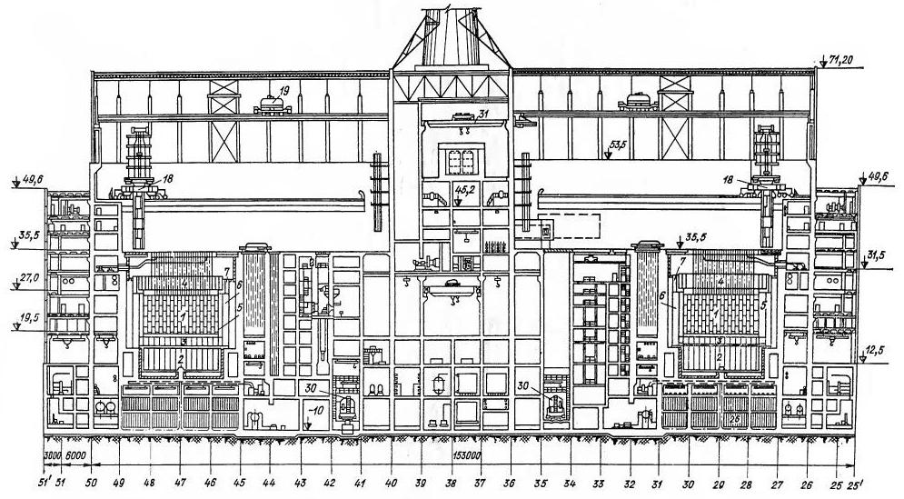
Fig. 2. The section for the reactor compartment of the nuclear power plant with RBMK-1000, included a zone of localization (for the designation of positions, see Figure 1)
1.5.2. Description of the site of the nuclear power plant and its construction.
The first stage of the Chernobyl NPP (two power units with RBMK-1000) was built in 1970-1977, and by the end of 1983, On the same site, the construction of two power units of the second stage was completed. At 1.5 km to the south-east of this site in 1981. The construction of two more reactors with the same reactors was started (the third stage of the NPP).
To the south-east of the site of the nuclear power plant directly in the valley of the river. Pripyat built a liquid cooling pond with an area of 22 km2, which provides cooling of condensers of turbines and other heat exchangers of the first four power units. The normal water level in the pond-cooler is taken at 3.5 m below the NPP site layout mark.
1.5.3. Data on the number of personnel at the nuclear power plant site during the accident.
On the night of April 25-26, 1986, there were 176 people on the site of the first and second queues of the Chernobyl Nuclear Power Plant - duty operational personnel, as well as workers of various workshops and repair services.
In addition, on site of the third stage of the nuclear power plant, 268 builders and installers worked in the night shift.
1.5.4. Data on equipment at the site operating in conjunction with the damaged reactor, and equipment used in the liquidation of the accident.
Each turn of the Chernobyl nuclear power plant consists of two power units with common systems for special water treatment and auxiliary facilities on the industrial site, which include: a storehouse for liquid and solid radioactive waste; Open switchgears; Gas economy; Reserve diesel-generator power stations; Hydraulic engineering and other structures.
The liquid radioactive waste storage facility constructed as part of the second stage of the nuclear power plant is designed for reception and temporary storage of liquid radioactive waste generated during the operation of the third and fourth units, as well as receiving the water of operating washes and returning them for processing. Liquid radioactive waste comes from the main building through pipelines laid on the lower tier of the overpass, and solid radioactive waste is fed to the storage along the upper corridor of the trestle by electric cars.
The reserve diesel power station (RDES) is an autonomous emergency source of power supply for systems that are important for the safety of each unit. Each diesel engine of the third and fourth units has three diesel generators with a unit capacity of 5.5 MW. To provide the work of the RDES, intermediate and base diesel fuel warehouses, pump pumping of fuel, emergency fuel draining tanks and oil are provided.
To ensure the technical water of responsible consumers requiring uninterrupted water supply, separate pump stations of the third and fourth units with reserve power supply from diesel generators are provided.
On April 25, 1986, all four power units of the first and second lines operated and auxiliary systems and facilities of the industrial site connected with their normal operation.

Comments
Commenting on, remember that the content and tone of your message can hurt the feelings of real people, show respect and tolerance to your interlocutors even if you do not share their opinion, your behavior in the conditions of freedom of expression and anonymity provided by the Internet, changes Not only virtual, but also the real world. All comments are hidden from the index, spam is controlled.