
Remote car security devices IR range
Remote car security devices IR range
In this section, we will consider security devices with remote control on infrared rays, allowing you to turn off the alarm without touching the car, and to stop delaying the transition of the system into a security mode. Time delays can sometimes be enough to "specialist" managed to open the hood and turn off the battery, and then in a quiet environment to deal with the alarm.
Of course, there are scanners of domestic and imported production, through which the combination of impulses, their duty cycle and period can reveal the signal code on infrared rays. Therefore, remote protection devices on IR beams will be considered, in which information coding based on other physical principles not available to modern scanners is used.
Infrared beam guard
This is a remote control system with frequency coding and a long-term exposure to the photodetector. Of course, frequency coding is not the top of perfection, but, nevertheless, it works effectively. To ensure that the frequency of the scanner at a certain moment does not coincide with the auto-guard frequency , a 2-second time delay is used, which almost completely eliminates the random selection of the frequency.
The autostore includes a remote control on infra-red LEDs of type AL107B, made according to the known scheme. Also included in the watchdog is an hourly chip K176IE12 and a quartz resonator Q 1 with a frequency of 32768 Hz for the formation of time intervals .
The main technical characteristics of the device:
Time of transition to the guard mode, s 20
The duration of the alarm sound, s 40
Frequency of interruption of the alarm signal, Hz 1
Alarm delay time, s 2
Current consumption in guard mode is not more than, mA 10
PCB dimensions, mm 60х65
Dimensions of the control panel, mm 25x30
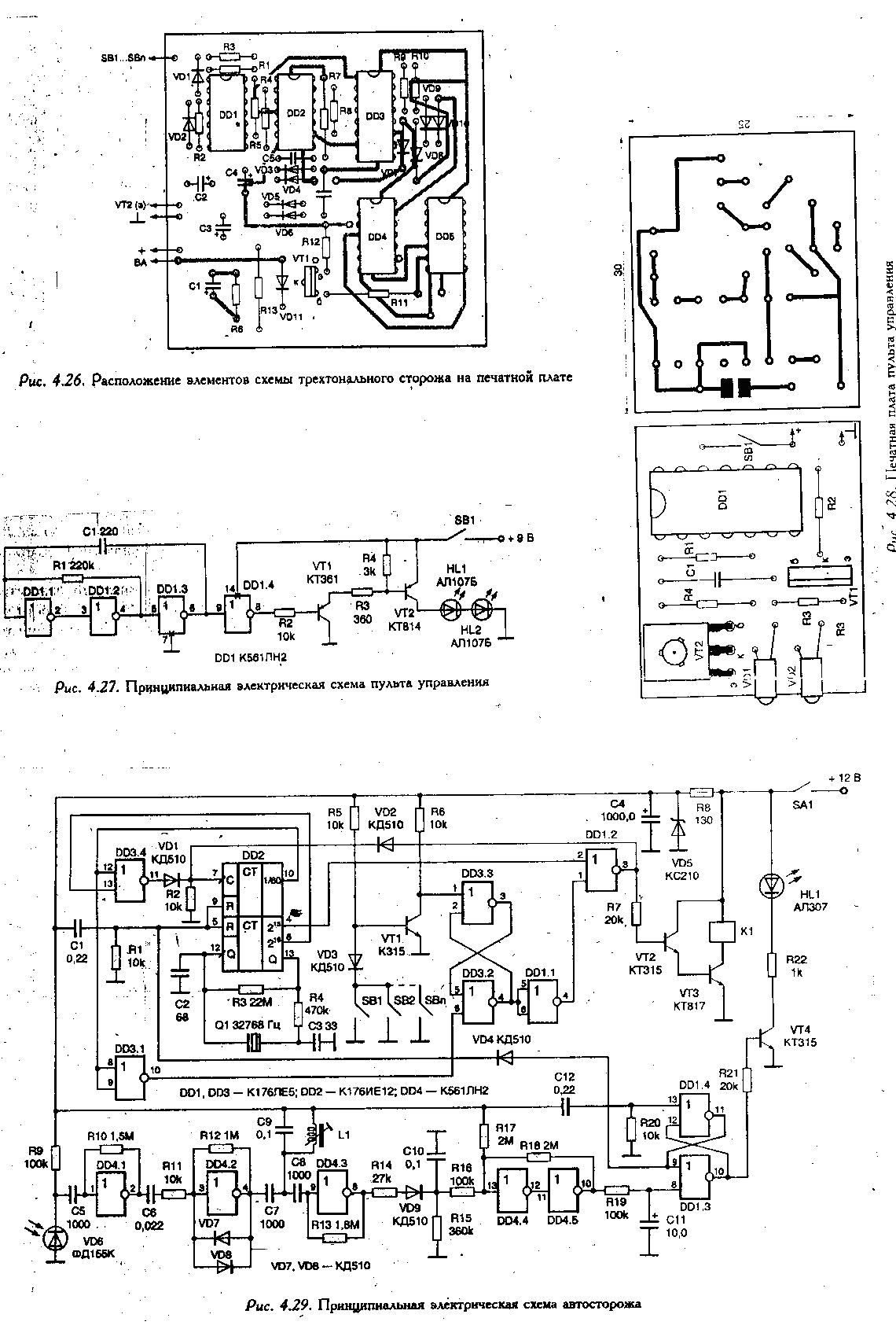
Schematic diagram of the remote control is shown in Fig. 4.27. The console includes a multivibrator on the elements DD 1.1 - DD 1.3, inverter DD 1.4, a pulse key on transistors VT 1, VT 2 and infrared light-emitting diodes VD 1, VD 2. The frequency control of the multivibrator is carried out by selecting the resistance of the resistor R 1. The printed circuit board of the control panel Is shown in Fig. 4.28. To power the remote, you can use the battery "Crohn", which will ensure its continued use.
A schematic diagram of the self-guard is shown in Fig. 4.29. The auto-guard contains the counter-time interval generator on the DD 2 chip, two flip-flops on the DD 1.3, DD 1.4 and DD 3.2 elements, DD 3.3, the receiver on the DD 4 chip with the photodiode VD 6 and the transistor key VT 2, VT 3.
When the power of the device is turned on by the tumbler SA 1 (before leaving the car), the capacitor C 1 sets its counters of the DD 2 chip to its initial zero state with its charging current. On pin 10 of the DD 2 chip at this time log. "0", which enters the input of the DD 3.4 element and opens it. From the output 6 of the DD chip 2 pulses at a frequency of 2 Hz pass the element DD 3.4 and go to the clock input C (pin 7) of the counter DD 2. At the same time, the zero level on the pin 10 of the DD 2 chip, inverted by the DD 3.1 element, blocks the trigger, Assembled on the elements DD 3.2 and DD 3.3, and prohibits the passage of the signal from the contact sensors SB 1 - SBn connected to the cathode of the diode VD 3, through the transistor VT 1, to the elements DD 1.1 and DD 1.2. In this state, the guard is located until the counter DD 2 counts 39 pulses at a frequency of 2 Hz. This time, equal to 20 seconds , gives the owner of the car the opportunity to get out of the salon and close all the doors. At the end of this time, a unit appears on output 10 of the DD 2 counter, which closes the DD 3.4 element And prohibits counting pulses with a frequency of 2 Hz on the counting input C DD 2. The same signal (log "1"), entering the inputs of the DD 3.1 element, unlocks the trigger on the elements DD 3.3, DD 3.2, and the circuit goes into the car security mode.
The door switches of the car can be used as contact sensors. The same pushbutton switches can be put on the hood and the boot lid. The cascade on the transistor VT 1 serves as an inverter and simultaneously protects the DD 3 chip from failure when a positive voltage is applied to its output at the time when the auto- guard voltage is turned off. When one of the contact sensors SB 1 - SBn is activated, the cathode of the diode VD 3 is closed to ground, the transistor VT 1 is closed and a positive potential is set on its collector that switches the trigger on the DD 3.3, DD 3.2 elements. At the same time, the log level is set on its output 4. " I ". From the output of the inverter DD 1.1 log. "0" goes to pin 1 of the DD 1.2 element and opens it. From output 4 of the DD 2 counter, the second pulses through the DD 1.2 element are fed to the output 7 of the DD 2 counter and the key to the transistors VT 2 and VT 3, which turns on the audio signal relay K 1 . Counter DD 2 counts 39 pulses arriving at pin 7, and after 40 seconds it is set to zero state (at terminal 10 - log "0"). Then, according to the scenario described above, there is a 20-second delay (like when the power is turned on), and the circuit goes back to the guard mode.
To turn off auto-guarding, a control panel is used that emits pulses in the infrared range . The photodetector, consisting of the photodiode VD 6 and the resonant amplifier on the elements DD 4.1 - DD 4.3, receives the signal from the remote control panel. The frequency to which the device responds is set by the contour elements L 1, C 9. Its resonance frequency must correspond to the frequency of the multivibrator of the console. From the resonant amplifier, the signal is fed to the dc driver. When the frequencies of the contour L 1, C 9 and the control panel multivibrator match at the output 10 of the DD 4.5 element, the log level appears. " I ". To exclude the actuation of the auto- guard when the device and scanner frequencies coincide randomly with the circuit R 19, C 11, a time delay of 2 s is generated.
After the capacitor C 11 is charged, the signal goes to the 8 trigger output on the DD 1.3, DD 1.4 elements, which on pin 11 forms a positive pulse, which is applied to the terminals 5, 9 of the DD 2 chip, and zeroes the counter. The turning-off time of the device is indicated by the LED HL 1.
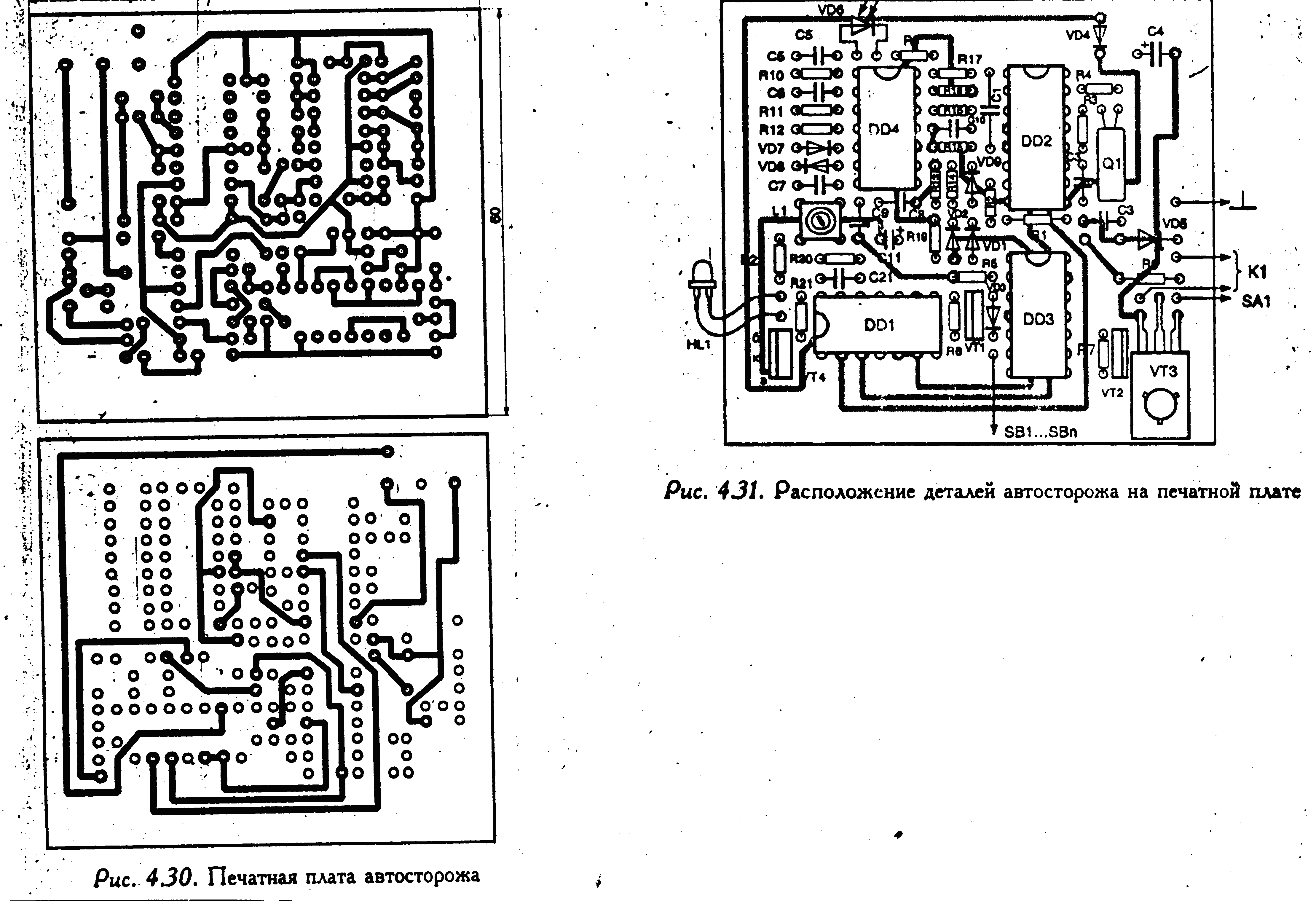
The circuit board of the auto- care device is shown in Fig. 4.30. The coil L 1 is wound on the core of the SBR-23 and contains, depending on the frequency, from 100 to 500 turns (from 16 kHz to 5 kHz, respectively) of the PEV-1 wire
The arrangement of the parts on the PCB is shown in Fig. 4.31.
The setting of the auto- guard is limited to setting the loop frequency by the elements L 1, C 9 and the frequency of the multivibrator of the remote control by matching the resistance of the resistor R 1, achieving a reliable and stable operation of the device.

Comments
When commenting on, remember that the content and tone of your message can hurt the feelings of real people, show respect and tolerance to your interlocutors even if you do not share their opinion, your behavior in the conditions of freedom of expression and anonymity provided by the Internet, changes Not only virtual, but also the real world. All comments are hidden from the index, spam is controlled.