Methanol production is a high-octane additive for gasoline
Brief information about methanol. Methanol, methyl alcohol, wood alcohol, carbinol, CH 3 OH - the simplest aliphatic alcohol, colorless liquid with a faint odor, reminiscent of the smell of ethyl alcohol. The boiling point is + 64.5 ° C, the freezing point is -97.8 ° C, and the density is 792 g / l. The limits of explosive concentrations in the air are 6.7-36% by volume. The octane number is more than 110. The ignition temperature is 467 ° C, the calorific value is 24000 kJ / kg - less than gasoline (44,000 kJ / kg), therefore the methanol consumption (in liters) will be about twice as high. As fuel is used in racing cars, for example in "Formula-1".
METHYL ALCOHOL is mixed in any concentrations with water, organic solvents and IUDOVIT, drunk 30 milliliters of methanol can be DEATH, unless urgent measures are taken! Vapors are also poisonous!
Traditionally, methanol was obtained by sublimation of wood. But a more promising way to get methanol - from natural gas. Later on, as this technology improves, other sources of raw materials, for example biomass (manure), are possible. Industrial methanol production methods are not yet effective enough to use methanol as a fuel, but in the coming decades, the price of oil will only rise and the situation may change in favor of alcohol fuel (especially when using cars on fuel cells). As you know, natural gas is almost 100% methane - CH 4 . In no case should it be confused with propane-butane balloon gas, the latter is a product of oil cracking and is used directly as an automotive fuel. However, this is done by many motorists, installing the appropriate equipment. And when using methanol, no additional equipment is required. We will describe in detail how, using methanol as fuel, it is possible to substantially increase engine power. In the meantime, we will only say that this is achieved by increasing the diameter of the main jets or by reducing the amount of air in the fuel mixture.
So, about the chemistry of the process of obtaining methanol from natural gas.
Methane under incomplete oxidation turns into carbon monoxide and hydrogen, this reaction is as follows:
2CH 4 + O 2 -> 2 CO + 4H 2 + 16.1 kcal.
A simpler process is carried out by the methane conversion reaction with water vapor:
CH 4 + H 2 0-> CO + 3H 2 49 kcal.
In the first equation, there is +16.1 kcal. This means that the reaction proceeds with the release of heat. In the second - with absorption. Nevertheless, we will focus on the second method of obtaining carbon monoxide and hydrogen. If these two components are present, methanol can be directly synthesized. The reaction follows the following formula:
CO + 2H 2 <=> CH 3 OH.
The difficulty is that the final product is obtained only at high pressure and high temperature (P> 20 atm, T = 350 degrees), but in the presence of a catalyst this process shifts to the right and at low pressure. The resulting methanol is removed from the reaction by cooling to condensation, and not condensed gases will be burned. If the hydrogen and CO residues are properly burned, no harmful substances are released (CO 2 and H 2 0 waste are harmless), so no exhaust devices are required. Then methanol is poured through the tube, necessarily with the sealing (!), Into the canister. As you can see, the chemical process is very simple, it is based on two reactions. Difficulties are only technological and security measures. We are dealing here with highly flammable and poisonous substances. You need to beware of both the explosion and the leakage of these gases. Therefore - it is necessary to strictly observe the technology and rules of treatment, which we will describe. To assemble the plant, you will need to buy: a sheet of stainless steel (1mm), a stainless steel tube seamless, an outer diameter of 6-8 mm, a wall thickness of at least 1 mm and a length of about 2 meters, a compressor from any household refrigerator (can be from landfills, But a worker). Well, needless to say, it will be necessary to have argon electric welding.
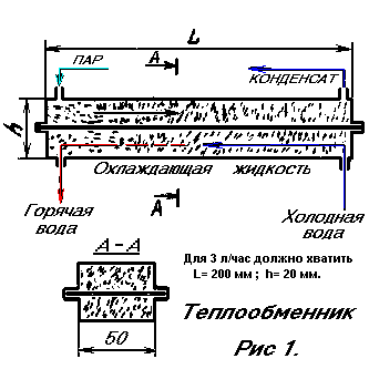
HEAT EXCHANGERS
Heat exchangers usually consist of tubes surrounded by a cooling medium. In everyday life they are called "coils". For liquids with a high thermal conductivity, such a heat exchanger may be acceptable. But with the gas situation is completely different. The fact is that at low speeds the flow of gas moves laminarly and practically does not exchange heat with the environment. Look at the smoke rising from the burning cigarette. This slender trickle of smoke and there is a laminar flow. The very fact. That the smoke rises up, speaks of its heat. And the fact that it remains a solid rod approximately to a height of up to 20 cm in height indicates that it retains heat. That is, at this distance, even at very low speeds, the gas flow does not have time to cool down, to exchange heat with air. It is because of the laminar flow that gas heat exchangers have to be constructed cumbersome. Inside their tubes, there are "drafts," which even at tens of meters practically do not give heat exchange. It is well known to those who ever drove moonshine. (Any experiment is useful!) A long, intensely cooled tube, condensate flows out of it, but steam also necessarily flows. Hence, heat transfer is not effective enough. The problem, however, has solutions and it can be simple. Fill the tube, for example, with copper powder (see Fig. 1). For a capacity of 10 l / h, the heat exchanger can be 600 mm long, and for 3 l / h 200 mm, h - 20 mm, should suffice. The particle sizes can vary, the optimum somewhere in the range of 0.5-1 mm. Considering the tasks of heat exchange, the material of the hull can be iron, copper, and aluminum, the stuffing material - copper, aluminum - that there is.
Then around each part of the metal a trickle of gas will form vortices. This immediately eliminates drafts and the flow becomes turbulent. Well, at the same time, the contact of gas with the cooled surface increases to a great extent. The copper powder filled in the tube constantly receives or gives off heat to the walls, and since the thermal conductivity of copper is about 100,000 times higher than the thermal conductivity of the gas, the gas will quickly assume the wall temperature if we intensively cool them. It should be taken into account that with decreasing particle sizes and increasing their number, the resistance to the gas flow also increases. Therefore, it is hardly possible to use particles smaller than 0.5-1 mm for a heat exchanger. Of course, flowing cooling water is advisable to flow towards the gas flow. This makes it possible to have a certain temperature at each point of the heat exchanger. Since the thermal contact is close to ideal, the temperature at the outlet of the condensed liquid will be equal to the temperature of the cooling liquid. This is the heat exchanger discussed here. The above sketch is none other than a distiller, it is also a moonshine machine, it is also a heat exchanger. The capacity of such a distiller is estimated at 10 liters per hour.
It can also be used for almost any purpose, including an installation for the production of normal ethyl alcohol (see Priority No. 1'91g and No. 1-2'92g). Such heat exchangers with huge capacity are hundreds of times smaller than existing ones.
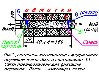 CATALYTIC PUMP (REACTOR, see fig. 2)
In the existing chemical gas processes, the usual catalyst goes in granules of a rather large size from 10 to 30 mm. The area of contact of gas with such balls is thousands of times smaller than if we used particles of 1-1000 microns. But then the patency of gas is very difficult. In addition, the smallest particles of the catalyst will soon fail due to surface contamination. We have found a way to increase the contact area of the gas with the catalyst, without hindering its patency in the reactor, and at the same time continuously purify the so-called "poisoning" of the catalyst itself. This is done as follows. The powder catalyst is mixed with ferromagnetic particles - iron or ferrite powder, which can be obtained by breaking magnets from faulty loudspeakers (note: ferrites lose magnetic properties at temperatures above 150 ° C), and since ferrites are very solid, it is their useful property Useful in the future (read below - not to specifically add abrasive powder).  A mixture of ferromagnetic powder with a catalyst is placed in a non-magnetic tube, for example, glass, ceramics, and can be made in aluminum or copper. Now see what the scheme can be. The windings of the coils are located outside the tube. Each of them is switched on via diodes, for example, as shown in Fig.
When the alternating current is switched on, the windings are switched alternately at a frequency of 50 Hz. At the same time, the ferromagnetic powder continuously compresses and expands the catalyst, providing pulsating gas permeability. If we include electromagnets in a three-phase network (see Fig. 4), then in this case the compressive pulsation of the compressions is ensured, and as a result of this, the gas will continuously contract in the longitudinal direction forward. Thus, the system works like a pump. At the same time - repeatedly mixing the gas, compressing and expanding it and increasing the intensity of the process by a thousandfold on the catalyst. In parallel, the catalyst particles rub against each other and a ferrite abrasive powder, which leads to their cleaning from the polluting films.
The scheme works as follows:
With a frequency of 50 Hz, the polarity changes on the power supply. The current alternately passes through the windings 1,3 and 2,4 (see Figure 2). In this case, a magnetic field appears in them, which magnetizes the ferromagnetic particles and forces them to interact with each other, involving the catalyst particles in motion. In this way, the passability through the small particles alternately occurs for the gas, replaced by the great resistance exerted by the compressed mass of particles. And most importantly: the activity of the catalyst, compressing and decompressing the reacting gas, for reasons not yet studied increases by an additional 20-50 times. The operation of the described catalytic reactor is equivalent to a reactor measuring 20-30 meters in size. Increase reactor capacity is possible, including windings in a three-phase network. At the same time, the system does not work as a valve, but as an active pump, combining all the positive effects of the first circuit and additionally forcing the gas to move in the direction of displacement of the phase shift. At such inclusion it is important to choose the correct phasing. So, in the reactor given here, the following positive factors work: 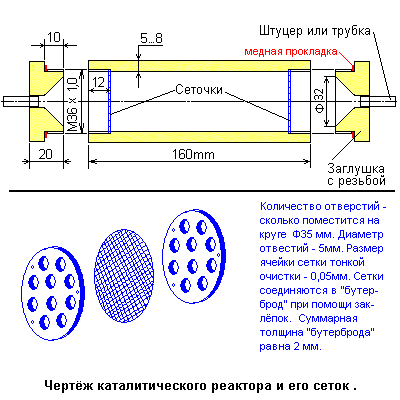
1. The increase in the area of the catalyst is 300-1000 times due to the decrease in particle size.
2. The catalyst is continuously cleaned from surface contamination.
3. Constant pulsations of the pressure of the reacting gases between the catalyst particles, and in the second scheme, there is additionally a transfer of gas inside the reactor itself.
The disadvantage of this reactor - increased resistance to gas flow - is eliminated by alternating compaction - the release of particles inside even-odd coils. One important detail: it is necessary to insulate the coils from the reactor vessel. In connection with this, as well as for practical reasons, the author of the site made the following changes (see right):
From a pig (bronze or brass) with a diameter of 50 mm, we cut the reactor vessel. The dimensions can be taken as before - 160 mm total length, working reactor length about 140 mm, inside. Diameter 33 mm, wall thickness approximately 5 ... 8 mm, i.e. Outer diameter of about 50 mm and the same diameter - plugs, their thickness of 20 mm and on each threaded thread M36h1,0mm and length of 10mm. All this must be done from the same material! To plugs in the holes are inserted and welded adapter nipples or simply connecting seamless steel tubes with an internal diameter of 6 ... 8 mm and a wall thickness of about 2 mm. This construction must be insulated from the outside with sheet asbestos and divided along its entire length into four sections using five partitions, also cut from sheet asbestos. To fix the partitions, it is possible to smear them with silicate glue, after drying, the copper wire (d = 0.15 mm) is wound in each section. The resistance measured by an ohmmeter for each section should be about 1200_Om. The windings are switched on via the voltage regulator (eg laboratory transformer - LATR) in order to avoid overheating of the windings, they must be cooled, for this purpose it is possible to lay glass tubes with a diameter of 6 ... 8mm under the windings, a forced blowing of the coils is possible, with control Temperature inside the reactor.
It should be noted that a similar scheme of the reactor (Fig. 2) was claimed for a patent (author - GN Vaks), it can work in any catalytic gas processes. Therefore, for chemists - this is not a home-made development, but a fundamentally new, yet not fully studied, but effective reactor. In all likelihood, the effects will be enhanced by the supply of rectangular pulses or high frequency oscillations.
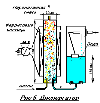
SYNTHETIC GAS PRODUCTION.
SYNTHESIS-GAS is a mixture of H 2 and CO, necessary for the production of methanol. Therefore, first we will consider the technology of synthesis gas. Traditional methods for producing CO and H 2 from methane (CH 4 ) are that methane is mixed with water vapor and in a heated state enters the reactor, where a measured amount of oxygen is added to the steam-methane mixture. The following reactions occur: [1] CH 4 + 20 2 <-> CO 2 + 2H 2 O + 890 kJ;
[2] СН 4 + Н 2 0 <-> СО + ЗН 2 - 206кJ;
[3] СН 4 + СО 2 <-> 2СО + ЗН 2 - 248кJ;
[4] 2H 2 + 0 2 <-> 2H 2 O + 484 kJ;
[5] СО 2 + Н 2 <-> СО + Н 2 0 - 41.2кJ.
As can be seen, some endothermic reactions - with heat absorption - and some exothermic - with excretion. Our task is to create a balance so that the reactions proceed with a controlled release of heat. So, in the beginning, a dosed mixing of H 2 O and CH 4 is required. Traditional methods of conducting this process are complex and cumbersome. We will saturate methane with water vapor by passing bubbles of this gas through heated water to 100 degrees Celsius, and that the bubbles are actively broken, place in their path solid ferrite particles 1-2 mm in size. But in this mass, sooner or later the bubbles find their way and then, practically without breaking, pass through the formed channel. To prevent this from happening, we put the ferrite particles and the mixing chamber into a solenoid with an alternating current supply. This is the essential difference between our dispersant (see Fig. 5). Under the influence of vibration of ferrite particles in a pulsating magnetic field, methane bubbles are constantly broken, pass a complex zigzag path and are saturated with water vapor. There are no rigid requirements to the solenoid, since it is powered by the LATR or from the light regulator (commercially available). The adjustment of the voltage on the solenoid is necessary to change the degree of saturation of methane with water vapor simultaneously by changing the magnetic field. The purpose of these changes will be discussed below. The number of turns in the coil can be from 500 to 1000. The diameter of the wire is 0.1-0.3 mm. The dispersant tube is taken from a non-ferromagnetic metal, so it will be heated in an alternating magnetic field. In addition, and methane enters the water heated. Therefore, a special heater for water is not required (note: erroneous opinion! Water must first be heated to a boil, for example with a gas heater, otherwise you do not get the right amount of water vapor). Another tank is needed for water make-up, since it is continuously consumed for the formation of a steam-methane mixture, for this purpose a drain tank from a standard toilet bowl whose draining hole is closed with a steel plate, with a welded drain tube, the end of this tube is inserted into the dispersant and bends downward to 180 ° (see Fig. 5), this is done for the purpose of safety, in order to avoid the ingress of methane gas into the tank. 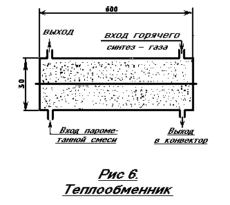
ATTENTION: it is necessary to arrange the tank in such a way that the water level in the mixer-dispersant does not rise above 150 mm, i.е. Up to half its height, this is due to the pressure in the gas network (= 150 mm of water column!), Otherwise the water will prevent the passage of methane gas into the dispersant. Also, the water must be cleaned of chlorine impurities before entering the tank. Standard water purification means for household purposes will cope with this.
The finished steam-methane mixture is heated to a temperature of 550-600 degrees in a HEAT EXCHANGER. The device of the heat exchanger (Fig. 6) has already been described in sufficient detail above (see Fig. 1). Therefore, we give only a refinement of the dimensions. The heat exchanger is made of stainless steel, it is necessarily brewed in an inert gas environment. Stainless steel tubes are attached to the body only by welding. The heat exchanger filler is made from 1-2 millimeter ceramic particles. This can be, for example, crushed porcelain dishes. It is necessary to fill the container sufficiently tightly, with obligatory shaking. Possible error: if the heat exchanger is insufficiently filled with ceramics particles, the gas will find its way, and the flows will be laminar, as heat exchange deteriorates.
ATTENTION: ALL SYSTEM MUST BE SEALED. No leaks! In the heat exchanger 3.2 (see Fig. 10), the temperatures are high! No seals are used - only argon welding.
THE MOST COMPLEX AND RESPONSIBLE UNIT OF THE UNIT IS A CONVERTER-REACTOR (see Fig. 7), where methane conversion occurs (converting it to synthesis gas). 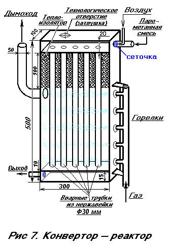 The converter consists of an oxygen-steam-methane mixer and reaction catalytic columns. In general, the reaction proceeds with the release of heat. However, in our case, for the process to begin, we carry out heating on the inlet pipes, since we carry out methane conversion according to the reaction [2]:
CH 4 + H 2 O <-> CO + 3H 2 - 206 kJ,
With the loss of heat, which means that it is necessary to supply heat to the converter. For this, we pass the steam-methane gas through the tubes heated by the burners. The converter works as follows:
The steam-methane mixture enters the chamber in which stainless steel tubes are welded. The number of tubes can be from 5 to 20 depending on the desired performance of the converter. The space of the upper chamber must necessarily be densely packed with coarse-grained sand or crushed ceramics or crumbs of stainless steel, particle sizes of 0.5-1.5 mm. This is necessary for better mixing of gases, and most importantly - for flame retardation. When the air is mixed with hot methane, a fire can occur. Therefore, in the upper chamber the packing is carried out with obligatory shaking and filling. The tubes and the collecting chamber (in Fig. 7-lower) are just packed with particles containing the catalyst-nickel oxide.
The mass fraction of nickel in the catalyst when recalculating to NiO should be at least 7.5 ± 1.5%. The residual content of methane in the conversion of natural gas with steam (steam: gas = 2: 1), at a temperature of 500 ° - 38.5%, and at 800 ° - no more than 1.5%. Mass fraction of "harmful" sulfur in terms of SO3, should not be more than 0.005%.
It is possible to manufacture such a catalyst (but it is better to find a ready-made, industrial catalyst). To do this, it is necessary to calcinate nickel particles in the air. If there is no pure nickel, then it can be prepared from nickel-containing 10-15-20-penny coins of the USSR. Erase them on a rough abrasive wheel or a small cutter. The ingress of abrasive in packing is allowed. The resulting powder is calcined and mixed in a ratio of 1/3 of the volume of the powder with 2/3 of the volume of ground ceramic (0.5 mm) or pure coarse-grained sand.
The gap between the upper parts of the tubes is filled by 10 cm with any high-temperature heat insulator. This is done so as not to overheat the upper chamber. There is an easy way to get such a heat insulator. The usual clerical silicate glue is mixed with 10-15% by weight of finely chalked chalk or talc or clay. Stir thoroughly. Pour the mixture in a thin layer and immediately cauterize with a blowtorch lamp. Boiling water in the glue forms a pumice-like white mass. When it cools, pour a layer of glue with chalk onto it again and treat it again with a flame. And so repeat until until they get the necessary layer of heat insulator. After the end of the assembly of the converter, it is placed in a steel box, which is necessarily insulated with a material that can withstand temperatures of up to 1000 degrees, for example, asbestos. Burners of injection type, can be any, from 5 pieces to 8. The more they are, the more uniform the heating. A system using a single burner is also possible. Its flame has several outlets through the holes in the pipe. Gas burners are commercially available, for example, those used for processing skis. There are also gas soldering lamps on sale, so we give only a general outline. Burners must be connected in parallel and regulated by a standard gas valve, for example, from a gas stove, but it is better to take an automatic regulator from a household gas stove - expensive, but reliable and convenient - with it you can set the desired temperature inside the converter reactor, thereby increasing the degree of autonomy Installation as a whole.
ANOTHER OF THE RESPONSIBLE NODES is an ejector mixer for supplying air and methane to the converter chamber (see Fig. 8). The ejector mixer of air and methane consists of two nozzles, one supplies methane saturated with vapors of water, and the other - an air ejector. Air comes from the compressor, the amount of it is regulated by the pressure valve (Fig.9.). The compressor can be practically from any household refrigerator, the pressure is regulated from "zero" to the required one, which will not be much higher than the pressure in the gas main (ie => 150 mmHg). 
The necessity of supplying air (oxygen) to the converter is due to the fact that according to the reaction [5], part of the hydrogen must be absorbed with the release of CO, thereby increasing the amount of carbon monoxide to the proportion of CO: H 2 == 1: 2, i.е. The number of moles (volumes) of hydrogen should be twice as large as the volumes of carbon monoxide ( note: the presence of excess air will lead to the synthesis of byproducts - acids, higher alcohols - "sivuhi" and other harmful components).
But the occurrence of CO 2 will occur through the reaction [1] with the release of a large amount of heat.
Therefore, at the beginning of the compressor process we do not turn on the screw and keep it screwed out.
The air is not served.
And as the camera warms up and the entire system is turned on, gradually, by turning on the compressor and screwing the pressure valve screw, increase the air supply and simultaneously reduce the flame on the burners. Control will be based on the amount of excess hydrogen at the exit of the methanol condenser (heat exchanger 3. and 3.1) through Wick (13-cm.ris.10), cutting it.
The wick for burning off the surplus synthesis gas is an 8 mm tube, 100 mm long, filled with copper wire along the entire length - so that the flame does not go down, into a can of methanol.
We dismantled all the units of the methanol production unit.
As is clear from the previous, the whole installation consists of two main units: a converter for creating synthesis gas (methane conversion) and a methanol synthesizer.
The synthesizer (catalytic pump, see Fig. 2) is described quite well above.
The only thing that should be added is the need to install a heat insulator between the pipe and the coil.
How to make a heat insulator, we reported when describing the manufacture of the converter (see Fig. 7).
RETURN TO THE GENERAL SCHEME OF INSTALLATION. The work of the general scheme: from the gas main, methane enters the heat exchanger (3.1) through the valve (14), heats up to 250-300 ° C, then enters the filter reactor (15), which operates on the principle of a catalytic pump (see Fig.2- Only the diameter of the tube = 8 cm), contains zinc oxide - to purify the gas of sulfur impurities and only then enters the mixer-dispersant (2), where it is saturated with water vapor. Water (distilled) is added to the dispersant continuously from the tank (1). The released gas mixture enters the heat exchanger (3.2), where it is heated to 500-600 ° C and goes to the converter (4). On the NiO catalyst at a temperature of 800 ° C, a reaction occurs [2]. To create this temperature, burners (12) work. After the temperature conditions have been established, the compressor (5) is turned on and the air is gradually supplied to the mixer (11). The pressure is increased by screwing the screw in the valve (8). At the same time, we reduce the flame on the burners (12) using the valve (14.2). The syngas produced at the outlet enters the heat exchangers (3.1, 3.2), where it is cooled to a temperature of 320-350 °. The synthesis gas is then fed to a methanol synthesizer (6), where a catalyst is converted from a mixture of the same amount of ZnO, CuO, CoO into methanol CH 3 OH. The mixture of gaseous products on the outlet is cooled in a heat exchanger (3.3). Which is described above (see Fig. 1) and enters the storage tank (10). In the upper part of it there is a tube - wick (13), where the products that do not react in the processes are burned. Ignition is necessary, necessary!
![Work of the general scheme. The methane enters the heat exchanger (3.1) through the valve (14), heats up to 250-300 degrees and passes through the filter reactor (15) to the dispersant mixer (2), where it is saturated with water vapor. Water is added to the dispersant continuously from the tank (1). The released gas mixture enters the heat exchanger (3.2), where it is heated to 500-600 degrees and goes to the converter (4). On the NiO catalyst at a temperature of 800-900 degrees, a reaction occurs [2]. The burners (12) are the working temperature.](/img/goods/1.files/met_16.gif)
SEVERAL ADVICES. Catalysts can be prepared by calcination of powder metals in air. Temperature measurement can be carried out with the help of thermal indications, which are currently quite common. Measurement should be carried out on the inlet and outlet tubes. If the thermo-color is not enough, you can make a tin-lead-zinc alloy. Under certain experimental proportions of mixing, they will have the required melting temperature. By applying the resulting alloys to the tubes and following their melting, it is possible to control the temperature with some error. If you do not allow the formation of gas pockets (ie, all the cavities are completely filled with the corresponding crumb), if the leaks have been eliminated and, most importantly, the wick is ignited in a timely manner and the wick is constantly burning (11), then the installation will be absolutely safe. Selecting catalysts can increase the thermal efficiency, increase the percentage of methanol yield. To achieve the optimum, experiments are required here. They are held in many institutions of different countries. In Russia, such research institutes include, for example, GIAP (State Institute of Nitrogen Industry). It should be borne in mind that the production of methanol from natural gas in compact installations is a new business, and many processes have not been sufficiently studied. At the same time, methanol - one of the most environmentally friendly and almost ideal fuels. And, most importantly, getting it is based on boundless and renewable resources - methane.


Comments
Commenting on, remember that the content and tone of your message can hurt the feelings of real people, show respect and tolerance to your interlocutors even if you do not share their opinion, your behavior in the conditions of freedom of expression and anonymity provided by the Internet, changes Not only virtual, but also the real world. All comments are hidden from the index, spam is controlled.