The device for anesthesia
Musical "anesthesia"
Ing . P. Wainboim, G. Mironenko, Leningrad
When I looked through the old archives, I came across this article and decided to share it. Once upon a time, as a student of the Gorky Radio Technical School, this device was the topic of a graduation project for my fellow student and fellow lab. The whole process of assembly and testing of the device passed before my eyes. The design of the assembled instrument was somewhat different: a high-quality reel record player (It seems "Jupiter 001-stereo") and slightly changed the circuitry . The initial skepticism toward this device was replaced by confidence in its effectiveness after the first tests in the dentist's office. In addition, we used this device simply to rest in the breaks between work. Interested persons can make such a device, based on the principle stated in the article below. And, using modern means of sound reproduction, for example CD-player, and modern circuitry , it is possible to create a compact device. So, the idea is - go!
Nikolay Bolshakov.
The device offered to the attention of readers is intended for anesthesia during the treatment of teeth and prosthetics. Everyone knows what unpleasant omissions arise when the tooth is treated with a drill. It is understandable therefore the interest of specialists in the problem of anesthesia in the treatment of teeth. At one time, many methods were proposed, but none of them was sufficiently effective. The most promising was the so-called method of sound analgesia. It consists that during treatment the patient listens to the musical program and white noise (a mix of all components of a sound spectrum of frequencies), submitted on head phones. Music beneficially affects the nervous system of the patient, and white noise extinguishes the focus of excitation in the cerebral cortex, caused by pain.
Device for Anesthesia (sound Analginizer ) Was Designed Leningrad Engineer P. Weinboim in collaboration with the doctor of the Military Medical Academy. S. M. Kirova G. Mironenko. In the creation of the device, great help was provided by the techniques of V. Kuznetsov and F. Gulyani- cius .
During the two-year operation in the dental department of the polyclinic of the Military Medical Academy, the sound analgesizer invariably received good patient feedback. The device was exhibited at the 17th Leningrad exhibition of creativity of radio amateurs-designers DOSAAF and was awarded a diploma of the I degree.
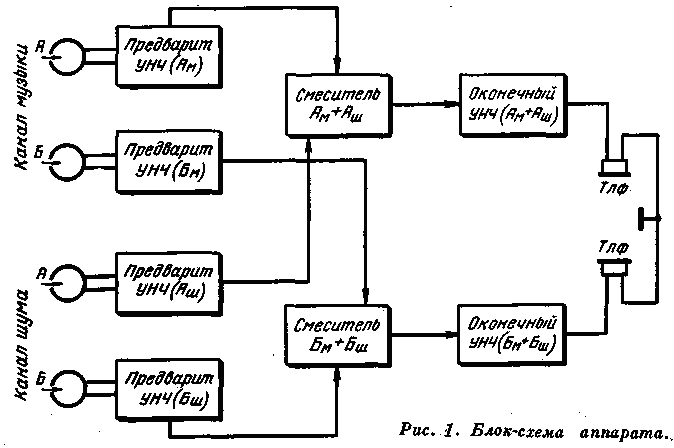
A block diagram of the sound analyzer is shown in Fig. 1. The device consists of an LF amplification unit, a mixer unit (patient panel), a power supply unit and a tape drive with an endless loop of magnetic tape. Its purpose is to simultaneously play the music program and white noise recorded on the four tracks of the tape. The device uses low- resistance two- channel reproducing heads with a working gap of 3 microns , a magnetic tape of type 6, a belt speed of 9.53 cm / s.
Correction of the frequency response in the cascade of the preamplifier LF allows to achieve high-quality reproduction in the frequency range up to 10 kHz .
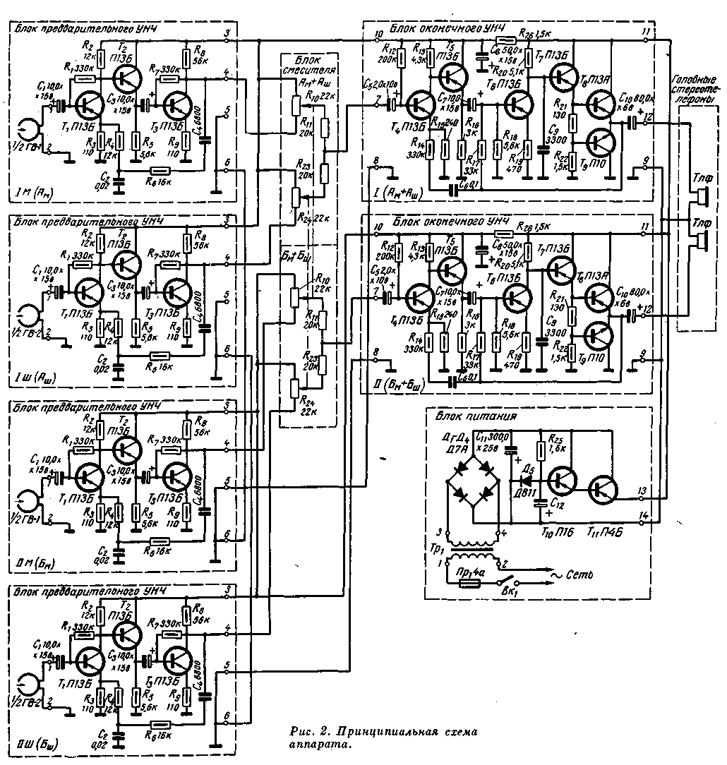
In Fig. 2 is a schematic diagram of an audio analyzer . All four signals are removed by magnetic heads from the tracks of the magnetic tape, the voltage of the signal goes to the corresponding preamplifier LF made on transistors T1-T3. Two preamp low-pass amplifiers amplify the music channel signals ( Am and Bm ), and the other two - noise channel signals ( Ash and Bash ). At the input of the low end amplifier using passive mixers (R10, R11, R23 and R24), music and noise are mixed in the required ratios. After mixing and amplifying the signal voltage with two low-end amplifiers (T4-T9), the signals Am + Am are fed to one of the headphones, and Bm + Bm to the other, resulting in a binary effect. If necessary, the patient can adjust separately the amount of music and noise from zero to maximum.
Three- stage preamplifier LF is made on transistors T1-T3 (P13B). The amplifier is covered by frequency- dependent negative feedback of 19 dB depth. The first stage of the amplifier is made according to the scheme with a common emitter. The playback head is connected to the input of the amplifier through the capacitor C 1 . The transistor used in the first stage should have a minimum noise level. To match the first stage with the next one, an emitter follower galvanically coupled to the first stage is used. The third cascade is similar to the first one. The negative feedback voltage is supplied from the collector circuit of the last transistor (T3) to the emitter circuit of the first through the elements C4R4R6. The output stage is loaded to the level controller, which is located in the remote mixer block.
The mixer unit, designed as a separate panel, is a rheostat divider consisting of two paired potentiometers (R10 and R24) and decoupling resistors R11, R23. Potentiometers act as regulators of the level of music and noise. Isolating resistors are necessary to eliminate the mutual influence of the outputs of the preamplifiers of LF. The resistances of these resistors are selected experimentally.
The terminating amplifier raises the signal level to the required level for normal playback in headphones. This amplifier should have a small coefficient of nonlinear distortion, high input impedance, low voltage gain and additional correction of the frequency response in the low frequency region (approximately 4 dB per octave).
The final amplifier is assembled on six transistors (T4-T9), five of which are of the type p-n-p , and the sixth (T9) is of the n- p-n type (P10).
The first and third stages, made on transistors T 4 and T 6 according to the scheme with a common emitter, amplify the signal voltage. The second and fourth stages on transistors T5 and T7 ( according to the scheme of the emitter follower) serve to match the output resistances of the previous stages with the input resistances of the subsequent ones.
The output stage is a two-stroke power amplifier, assembled in a common-collector circuit with transistors of different conductivity. This makes it possible to dispense with a phase-inverted cascade. The amplifier is covered by deep feedback (26 dB ), which sharply reduces the coefficient of nonlinear distortion. The feedback voltage depends on the frequency ( frequency-dependent feedback), so that an additional correction of the frequency characteristic of the reproduction channel in the low-frequency region is achieved. In addition, the input resistance of the final amplifier covered by feedback increases. The amplifier is not critical to the load.
The power supply of the device contains a voltage regulator on the transistors T10, T11. The reference voltage is removed from a Zener diode of type D811. The rectifier was assembled on a bridge circuit using four D7A germanium diodes. The whole device is powered from the AC mains through a power transformer.
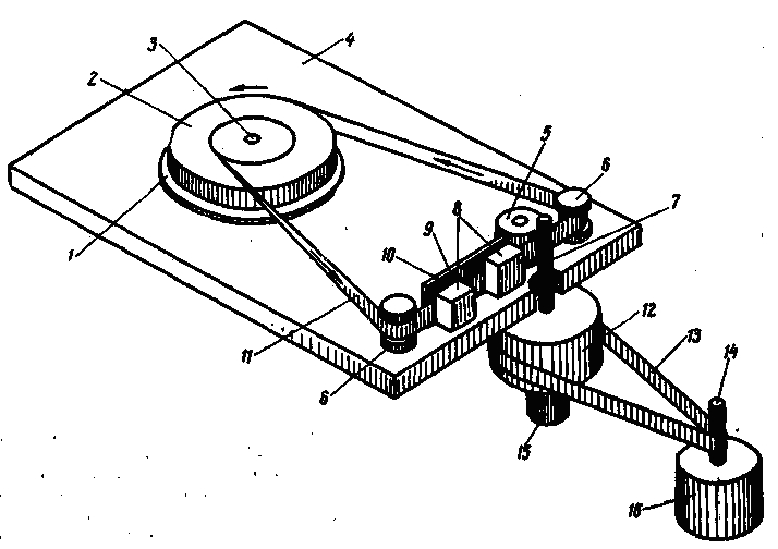
The kinematic scheme of the tape mechanism is shown in Fig. 3. The use of an endless loop of magnetic tape placed in a special cassette made it possible to simplify the tape drive mechanism and use a low-power engine of the EDG-1M type.
The cassette of the device is a plastic box with a tape roll length
For reliable contact of the magnetic tape with the heads a special felt clip is used, which is removed at the moment of switching on the device.
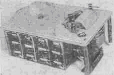
Structurally, the whole apparatus is made in the form of a separate block (Fig. 4).
Machine weight
On the upper panel of the device, a cassette with a device for mounting and pressing the magnetic tape to the shaft, two stereo heads and an on / off switch (Fig. 5) are reinforced. C The thermal heads are closed with a safety cover.
Under the panel is a board made of B-95 alloy
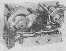
Preliminary amplifiers of reproduction are executed in the form of the separate block. It is mounted on a box-shaped steel chassis. The dimensions of the chassis are 160X80X40 mm. All four amplifiers are assembled on textolite boards and separated from each other by screens (Figure 5).
The final amplifiers are assembled on two PCBs and are located on the other side of the installation of the preamplifiers. The control panel is made as a separate unit. The structure of this unit includes two dual potentiometers, playing the role of level controllers, and output pads for connecting the doctor's and patient's head phones.
Fig. 3 . Kinematic scheme of the tape drive mechanism: 1. A shaped disk, 2. Roll Films, 3. Sleeve Disc, 4. Bottom, 5. Clamping roller, 6. Guiding column, 7. Driving shaft, 8. Magnetic reproducing stereo head , 9. Clamping Strap, 10. The felt Pad, 11. Loop Magnetic Tape. 12. Flywheel. 13. The lavsan belt, 14. The axis of the engine, 15. The thrust bearing of the flywheel, 16. The electric motor.

You can also support shram.kiev.ua, press:
It will not be superfluous for your friends to learn this information, share their article with them!
Comments
When commenting on, remember that the content and tone of your message can hurt the feelings of real people, show respect and tolerance to your interlocutors even if you do not share their opinion, your behavior in the conditions of freedom of expression and anonymity provided by the Internet, changes Not only virtual, but also the real world. All comments are hidden from the index, spam is controlled.