Wireless microphone-bug
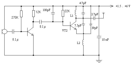
L2 = 100 turns on the MLT resistor - 0.25 or to improve the efficiency it is better to take a ferrite core of the brand 20 HF in diameter 2-3 mm and a length of 5-10 mm (its inductance should be ~ an order of magnitude greater than the inductance L1).
The original version of the circuit was tested on CT 3130A9 transistors. But, since their limiting frequency is about 150 MHz, for the output stage I chose a very good microwave transistor 2T 657A2 (and KT 3130A9 and 2T 657A2 have SMD enclosures).
In principle, here comes any high-frequency (F1> 150 MHz), the same infamous KT315.
For supply voltages above 5 V, a resistor of 30 ohms is connected in series with L2 to limit the collector current VT2.
The output power of the transmitter is approximately 10 mW (2T 657A2, 3 V).
The microphone is taken electret, condenser type MKE-3 or better, of course, the microphone "Pine" M1 - A2. I want to note, "Pine" does not like supply voltages greater than 3 V.

Comments
When commenting on, remember that the content and tone of your message can hurt the feelings of real people, show respect and tolerance to your interlocutors even if you do not share their opinion, your behavior in the conditions of freedom of expression and anonymity provided by the Internet, changes Not only virtual, but also the real world. All comments are hidden from the index, spam is controlled.