
Simple universal lathe
| Simple universal lathe |
|
This homemade universal machine (Figure 1) is easy to manufacture and work reliably. With its help, you can grind any cutting tools. At the free end of the motor shaft, instead of a nozzle for abrasive and grinding wheels with a special adapter, you can install a standard drill chuck, which allows you not only to drill holes, but also to milling grooves in wooden parts. The engine for the machine is taken from the washing machine "Vyatka" of the old model. 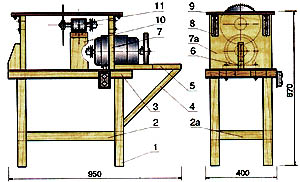 Fig. 1. Simple universal machine: 1 - a leg (4 pieces); 2, 2a - ties (4 pcs.); 3 - plate of the frame; 4 - a hinge (2 pcs.); 5 - table-bench; 6 - headscarf; 7.7a - side racks [2 pcs.); 8 - bracket (4 pcs.); 9 - table top of the saw table; 10- the bracket of the shaft assembly; 11 - the working shaft assembly. 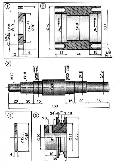 Fig. 2. The operating shaft assembly and its main parts: 1 - the cover of the case; 2 - housing; 3 - shaft; 4 - a washer of fastening of circular saws (2 pieces); 5 - a pulley; 6 - nozzles for installing an abrasive wheel. 7 - nozzles for a drill chuck. 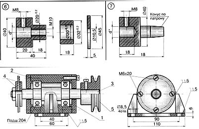 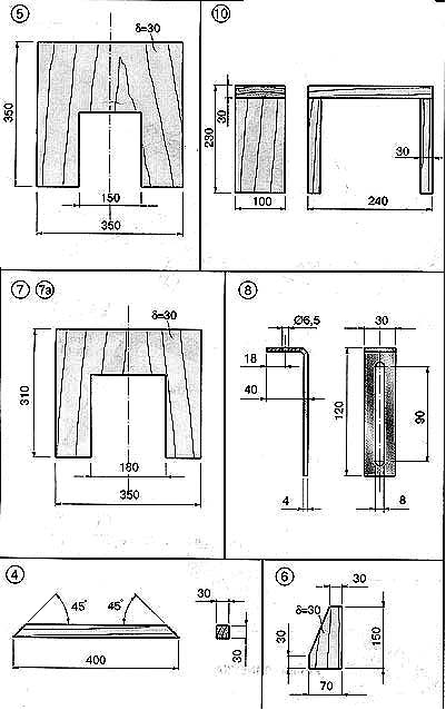 Fig. 3. The main details of the saw table and workbench (the numbers of the positions correspond to Figure 1); 4 - a hinge (2 pcs.); 5 - table-bench; 6 - headscarf; 7.7a - side racks (cut-out only in part 7); 8 - bracket; 10 - the bracket of the shaft assembly. The tools and the electric drive of the machine are placed on the frame. Its main parts can be either metal (corners or rectangular pipes) and wood. Of course, it's easier to make a frame of wood, then all the details of the construction can be collected on the screws. The base of the frame is a carpenter's plate 3 (see Figure 1) with a thickness of 50 mm and a size. 400x700 mm. Legs 1 (4 pcs.) Are made of blocks 50x50 mm long 500 mm, and screeds 2 and 2a (4 pcs.) - from blocks 50x50 mm (single 500 and 300 mm respectively). On the stove plate 3, the electric motor is bolted. It has shaft departures on both sides of the body. It is very convenient. At one end of the shaft, a variety of abrasive wheels for grinding, grinding or polishing, or a cartridge for drilling and grooving grooves, are installed using special nozzles (Fig. On the other side, the V-belt drive pulley (under the O (Z) drive belt of the operating shaft of the circular saw.The bearing assembly of the working shaft (the construction and parts of this assembly are shown in Figure 2) is bolted to the bracket 10. The belt tension is regulated by a set of gaskets for the bearing assembly. At the end of the working shaft 3 (see Fig. 2), thread M12 is cut to fix the longitudinal and transverse circular saws. In addition to saws, it is possible to install cut-off wheels for cutting metal or special disk cutters. The table top of the saw table 9 (see Fig. 1) is a sheet of plywood 8 mm thick and 350x450 mm in size. It rests on two vertical posts 7 and 7a, fixed on plate 3. In the table top a groove for cutting out the saw blade is cut out. The depth of cut can be changed by moving up and down the table tops 9 on the brackets 8, which are fixed in the desired position with screws. The dimensions of the main parts of the saw table correspond to those shown in Fig. 1. In Fig. 3 shows the dimensions of the table-bench 5, which is intended for sharpening, drilling and milling grooves. For the safe operation of the saw blade area and grinding tools must necessarily have a protective fence (not shown in the figures). In addition, when sharpening and drilling, the belt drive must be disconnected. |

Comments
When commenting on, remember that the content and tone of your message can hurt the feelings of real people, show respect and tolerance to your interlocutors even if you do not share their opinion, your behavior in the conditions of freedom of expression and anonymity provided by the Internet, changes Not only virtual, but also the real world. All comments are hidden from the index, spam is controlled.