
Spot Microwelding
| Spot Microwelding |
|
A portable small-sized electric welding machine with a remote welding gun is designed for welding stainless steel sheets and ordinary steel with a thickness of 0.08 ... 0.15 mm to massive steel parts, as well as for welding steel wires with a diameter of up to 0.3 mm. It can be used in many branches of the national economy, for example, in the manufacture of thermocouples, for welding to metal structures of tensometric sensors pre-glued to steel foil, and in many other cases. The appearance of the welding machine is shown on the 3rd s. Tabs (top). The weight of the power unit of the device is about 8 kg, dimensions-225х135Х120 mm. As can be seen from the basic electrical circuit, (Fig. 1), the device consists of two main components: an electronic relay on a V16 trinistor and a powerful welding transformer T2. Fig. 1 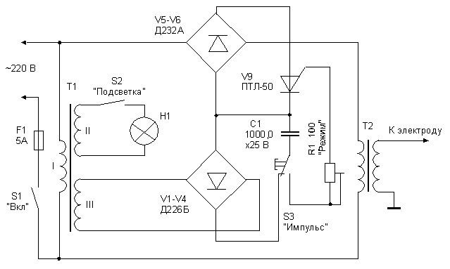 A welding electrode is connected to one of the leads of its low-voltage secondary winding, the second terminal is reliably connected to the more massive of the two welded parts. The mains of the welding transformer is connected to the mains via a diode bridge V5-V8, in the diagonal of which the transistor V9 of the electronic relay is switched on. The low-power auxiliary transformer T1 feeds the trinistor control circuit (winding ///) and the spotlight lamp HI (coil //). The device works as follows. When the contacts of the switch S1 "On" are closed The supply voltage of 220 V is applied to the primary winding of the transformer T1 of the control unit of the transistor. The capacitor C1, which is connected through the closed contacts of the switch S3 "Impulse" to the rectifier bridge V1-V4, is charged. The primary winding of the welding transformer T2 is de-energized, since the trinistor V9 is closed. When the switch S3 is pressed, the charged capacitor C1 is connected to the control electrode of the trinistor V9 via the variable resistor R1. The discharge current of the capacitor opens the transistor, and the mains voltage goes to the primary winding of the welding transformer T2. If the secondary winding of the welding transformer is connected to the parts to be welded, a powerful current pulse arises in it, which causes a strong heating of the metal and the point of contact of the welding electrode. The duration of the current pulse depends on the parameters of the time-consuming circuit R1C1. At the nominal values of the elements of this target, indicated on the diagram, the maximum pulse duration ti (without taking into account the internal resistance of the transistor) is approximately 0.1 s. During this time, the current in the secondary winding can reach 300 ... 350 A. This is quite enough for a strong welding to massive structures of foil parts up to 0.15 mm thick, for example, alloy steel 1X18H10T. The device returns to the initial state automatically after the discharge of the capacitor C1 is completed. The optimum welding mode is set by trimmer R1 "Mode". Structurally, the welding machine consists of two parts: a power unit and a welding gun, which are connected together by a flexible cable using a multi-pin connector. On the chassis of the power block are placed almost all the elements of the device. The chassis design and its main dimensions are shown on the masonry. Fig.2. Power unit casing 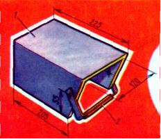 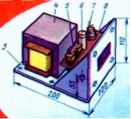 Fig.3. Power unit design On the basis of the chassis 3, there is a welding transformer 4 and bars with diodes V1-V8. To the front panel of the chassis is attached bracket 8 with auxiliary transformer 5 mounted on it, capacitor 6 and trinistor 7. On the front panel, mount one of the parts of the connector (in the rectangular hole) of the connecting cable, the variable mode setting resistor, the network toggle switch, the pin part of the power cord connector And clamp for connection, the more massive of welded parts. Casing 1 is made of duralumin with a thickness of 2.5 mm and is equipped with a handle 2 for carrying. The device of the welding gun is shown in the figure. Fig.4. Welding gun device 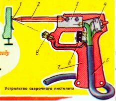 The body 7 of the pistol is made in the form of two identical in shape parts, cut from a sheet of textolite 12 mm thick. The holder 3 of the welding electrode is mounted in the housing. 2. The lamp 8 of the illumination with the button switch 4 "Backlight", the microswitch 6 "Impulse". Connecting cable 5 is a flexible twenty-four-wire cable in rubber insulation with an outer diameter of 11 mm and a cross-section of each wire of 0.75 mm square. Five cable wires are used to connect the microswitch and the backlight, and the remaining nineteen are soldered directly to the electrode holder 3. The holder is made of a copper bar of rectangular or square cross-section. The electrode 2 is a copper rod with a diameter of 8 mm. The electrode must be securely fixed in the holder. Along with this, the possibility of changing the electrode must be provided. To weld the foil, the sting of the electrode is sharpened by a cone transforming into a sphere with a diameter of 1 ... 1.5 mm. To weld the wire, use an electrode with a flat working highlander. Installation of the gun starts with the cutting of the cable. Nineteen cable conductors are carefully cleaned, twisted together, handled and sealed in the hole of the electrode holder 3. The remaining five wires are cut to the required length and soldered to the microswitch 6 and the illumination lamp 8. The other end of the cable is inserted into the insert of the type A plug-in connector into 20 pins (cable construction, see the photo on the tab). The pistol uses a microswitch MPZ-1T, a CM-34 illumination lamp at 6V, 0.25A with a fittings provided with a small lens, and a button for switching on the backlight from the table lamp. On the front panel of the power unit chassis, the mating connector of the connecting cable is installed. Five corresponding contacts of the connector are connected to one or other circuits of the device, and the others are connected in parallel and connected to one of the terminals of the secondary winding of the welding transformer. Fig.5. Appearance of the device 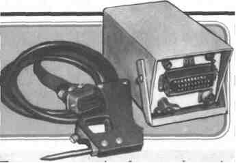 The magnetic circuit of this transformer is taken from plates Ш40, the thickness of the set is 70 mm. The primary winding contains 300 turns of PEV-2 wire 0.8. The secondary winding of this transformer consists of 10 turns of insulated wire or a bus with a cross section of at least 20 mm2 (in the described design this winding is made of two stranded conductors 4 mm in diameter, wound simultaneously). A "grounding" connecting conductor of the secondary winding is produced of the same cross-section. Its length should not be chosen greater than 2 ... 2.5 m. The transformer T1 can be any, providing on the secondary windings voltage 8 ... 10 V (for charging the capacitor C1) and 3 ... 6 V (for powering the lamp) . In this design, a magnetic circuit was used from the transformer of the children's railway (section 10х10, L-shaped plates). The network winding /, containing 8000 turns of PEV-2 wire 0.08, the winding // - 330 turns of PEV-2 wire 0.3 and the winding /// - 350 turns of PEV-2 wire 0.2 are placed on it. The clamp, connected to the lower (according to the scheme) terminal of the secondary winding of the transformer T2, is mounted on the chassis without insulating gaskets. When manufacturing transformers, it must be borne in mind that the quality of insulation of their windings depends on the safety of the operator. Therefore, on top of the primary (network) windings of transformers, no less than 4-6 layers of lacquer or paper impregnated with paraffin should be applied. The welding machine uses a trimmer PPZ-11, a capacitor K50-3, a network switch TP1-2. It should be noted that the use of the PTL-50 trinistor is due solely to the desire to ensure high reliability of the device and trouble-free operation in severe climatic conditions and with large variations in mains voltage. With some deterioration in the quality of welding in the device can be used trinistory series KU202 with indices K, L, M or H. In this case, it is necessary to reduce the resistance of the resistor R1 to 50 Ohm, and the capacity of the capacitor C1 to double. Correctly assembled apparatus starts working immediately, without any adjustment. The quality of the weld (points) is checked as follows. A strip of steel foil with a width of 10 ... 12 mm is welded to the surface of the steel bar scraped off from three to five points, and then torn off using pliers. At the welding points on the foil there must remain openings with a diameter of 0.5 ... 0.8 mm, which indicates that the separation occurs not at the place of welding, but around it. If the foil comes off at the welding site, the welding current is selected by a tuning resistor "Mode". When selecting a current, it is necessary to take into account that the quality of the seam deteriorates with increasing pressure on the electrode. It should also be noted that, according to reference data, the DC voltage that must be supplied to the control electrode of the PTL-50 tri-transistor for opening it is 8 V. However, the quality of the seam is significantly improved if this voltage is increased to 12 ... 15 V (charged capacitor voltage C1). The order of work with the device. First of all, they "ground" the casing of the welding machine and the structure to which the part is to be welded. Working with the welding machine should wear protective rubber gloves and stand on a rubber mat. The apparatus is turned on, the welded part is applied to the structure and pressed tightly by the tip of the welding gun electrode at the point where it is necessary to obtain the weld point. Click on the "trigger" of the pistol (on the microswitch button), after 1 ... 1.5 s remove the pistol from the part and place a sting on the next point. In those cases, where necessary, include a backlight. When using the device in production, it must necessarily be adopted by the local safety commission. In conclusion, it should be pointed out that the capabilities of the device can be significantly expanded. If, for example, a coppered graphite electrode with a diameter of 6 ... 8 mm is used, copper tinned conductors with a diameter of up to 0.3 mm can be welded. Very well, such conductors are welded to any tinned and silvered parts, as well as to copper non-coated foil. It is possible, for example, to weld thin conductors to the foil of a printed circuit board without the use of flux. Good results were obtained by welding sheets of very thin copper foil. In this case, it is necessary to select the length and shape of the graphite electrode tip by an experimental test. If it is necessary to weld parts from thicker sheet metals, the welding transformer will have to be replaced with a more powerful one. For example, to connect steel sheets with a thickness of 0.5 ... 0.7 mm, a transformer with a cross-section of magnetic circuit of at least 65 ... 70 cm2 is required. The primary winding of such a transformer should contain 160-165 turns of PETV wire with a diameter of 1.62 ... 1.7 mm, and a secondary winding of 4.5 turns of a copper busbar with a section of at least 90 mm2 (based on a welding current of 1400 ... 1800 A). The diameter of the electrode should be increased to 18 ... 20 mm. In this case, the current in the primary winding of the transformer is about 45 A at the moment of the welding pulse. Therefore, the diodes V5-V8 will need to be replaced by more powerful ones, for example VL-50. Trinistor V9 should also be designed for a forward current of at least 50 A. Experience, however, shows that for welding steel sheets up to 0.5 ... 0.7 mm thick, it is perfectly permissible to use a PTL-50 trinister without an additional radiator, since the welding The impulse is very short. In order to ensure a nominal mode when welding metals of different thicknesses (from 0.08 to 0.7 mm), the apparatus needs to provide for a wider regulation of the welding current. Most expediently, instead of the capacitor C1, use a set of three capacitors with a capacity of 1000 μF each, switched by a switch either sequentially (for thin-sheet metals) or in parallel. |

Comments
When commenting on, remember that the content and tone of your message can hurt the feelings of real people, show respect and tolerance to your interlocutors even if you do not share their opinion, your behavior in the conditions of freedom of expression and anonymity provided by the Internet, changes Not only virtual, but also the real world. All comments are hidden from the index, spam is controlled.