Principle of operation of the electronic counter
To calculate the electrical energy consumed for a certain period of time, it is necessary to integrate instantaneous values of active power in time.
For a sinusoidal signal, the power is equal to the product of the voltage on the current in the network at a given time.
Any electric energy meter works on this principle.
In Fig.
1 shows a block diagram of an electromechanical counter.
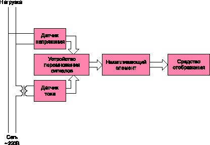
Fig. 1. Block diagram of an electromechanical electric energy meter
The implementation of a digital electricity meter (Figure 2) requires specialized ICs capable of multiplying signals and providing the value obtained in a form convenient for the microcontroller.
For example, the active power converter is the pulse repetition rate.
The total number of pulses received, counted by the microcontroller, is directly proportional to the consumed electricity.
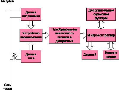
Fig. 2. Block diagram of a digital electricity meter
No less important role is played by all kinds of service functions, such as remote access to the meter, to information about stored energy and many others.
The presence of a digital display, controlled by the microcontroller, allows you to programmatically set various modes of output information, for example, display information on energy consumption for each month, at different rates, and so on.
To perform some non-standard functions, for example, level matching, additional ICs are used.
Now we have started to produce specialized ICs - power converters to frequency - and specialized microcontrollers containing similar converters on a chip.
But, often, they are too expensive for use in household and induction meters.
Therefore many world manufacturers of microcontrollers develop specialized microcircuits intended for such application.
Let's pass to the analysis of construction of the simplest version of the digital counter on the cheapest (less than dollar) 8-bit microcontroller Motorola.
In the presented solution all minimally necessary functions are realized.
It is based on the use of an inexpensive power converter IC to the pulse frequency KR1095PP1 and the 8-bit microcontroller MC68HC05KJ1 (Figure 3).
With this structure, the microcontroller needs to summarize the number of pulses, display information on the display and perform its protection in various emergency modes.
The counter in question is actually a digital functional analog of existing mechanical meters, adapted to further improvement.
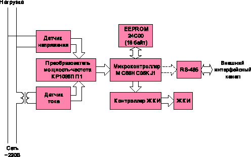
Fig. 3. Basic units of the simplest digital electricity meter
Signals proportional to the voltage and current in the network are removed from the sensors and fed to the input of the converter.
The converter IC multiplies the input signals to obtain an instantaneous power consumption.
This signal is fed to the input of the microcontroller, which converts it into Wh, and, as the signals accumulate, the meter readings change.
Frequent power failures lead to the need to use the EEPROM to store the meter reading.
Since power failures are the most typical emergency situation, this protection is required in any digital meter.
The algorithm of the program (Figure 4) for a simple version of such a counter is quite simple.
When the power is turned on, the microcontroller is configured according to the program, reads the last stored value from the EEPROM and displays it on the display.
Then the controller goes into the counting mode of the pulses coming from the converter IC, and, as each W · h accumulates, increases the meter reading.
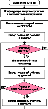
Fig. 4. The algorithm of the program
When writing to the EEPROM, the accumulated energy value can be lost when the voltage is cut off.
For these reasons, the value of the stored energy is written to the EEPROM cyclically one after the other after a certain number of changes in the meter reading, programmed, depending on the accuracy required.
This avoids the loss of data on accumulated energy.
When the voltage appears, the microcontroller analyzes all values in the EEPROM and selects the last one.
For minimal losses, it is sufficient to record the values in steps of 100 Wh / h.
This value can be changed in the program.
The circuit of the digital calculator is shown in Fig.
5. Connector X1 connects the power supply 220 V and load.
From the current and voltage sensors, the signals are fed to the microcircuit of the KR1095PP1 converter with the opto-coupler of the frequency output.
The basis of the counter is the microcontroller MC68HC05KJ1 of Motorola, manufactured in a 16-pin package (DIP or SOIC) and having 1.2 KB of ROM and 64 bytes of RAM.
To store the accumulated amount of energy in the event of a power failure, the Microchip small size 24S00 (16 bytes) EEPROM is used.
The display uses an 8-bit 7-segment LCD, controlled by any inexpensive controller, communicating with the central microcontroller using the SPI or I 2C protocol and connected to the X2 connector.
The implementation of the algorithm required less than 1 KB of memory and less than half of the I / O ports of the MC68HC05KJ1 microcontroller.
Its capabilities are enough to add some service functions, for example, combining meters into the network via the RS-485 interface.
This function will allow you to obtain information about the stored energy in the service center and turn off the electricity in the absence of payment.
A network of such meters can be equipped with a multi-storey residential house.
All indications on the network will be sent to the dispatch center.
Of particular interest is a family of 8-bit microcontrollers with a FLASH memory located on the chip.
Since it can be programmed directly on the assembled board, the program code is protected and the software can be updated without installation work.
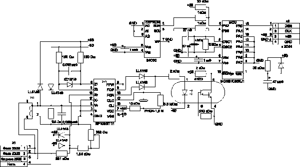
Fig. 5. Digital calculator for a digital electricity meter
Even more interesting is the electricity meter without external EEPROM and expensive external non-volatile RAM.
In it, you can record in the event of an emergency the readings and service information in the internal FLASH memory of the microcontroller.
This also ensures the confidentiality of information, which can not be done with an external crystal that is not protected from unauthorized access.
Such energy meters of any complexity can be realized with the help of microcontrollers from Motorola HC08 family with FLASH-memory located on the chip.
The transition to digital automatic systems for accounting and control of electricity is a matter of time.
The advantages of such systems are obvious.
The price of them will constantly fall.
And even on the simplest microcontroller, such a digital electricity meter has obvious advantages: reliability due to the complete absence of rubbing elements;
Compactness;
The possibility of making the case taking into account the interior of modern residential buildings;
Increase in the period of verification several times;
Maintainability and ease of maintenance and operation.
With small additional hardware and software costs, even the simplest digital meter can have a number of service functions that are not available for all mechanical ones, for example, the implementation of multi-tariff payment for consumed energy, the possibility of automated accounting and control of consumed electricity.


Comments
Commenting on, remember that the content and tone of your message can hurt the feelings of real people, show respect and tolerance to your interlocutors even if you do not share their opinion, your behavior in the conditions of freedom of expression and anonymity provided by the Internet, changes Not only virtual, but also the real world. All comments are hidden from the index, spam is controlled.