Gas flow meters
Household and household gas meters produced by industry
- SG-1, SGBM-1,6
- Gallus 2000 G1,6, G2,5, G4
- NPM-G1,6, NPM-G2,5, NPM-G4
- BK-G1,6, BK-G2,5, BK-G4
- СГК-1,6, СГК-2,5, СГК-4
- СГК-1,6, СГК-2,5, СГК-4 (Т) *
- "Helios" G1,6 "Helios" G2,5 "Helios" G4
- SGB-G2.5, SGB-G4-1
- GGB-G2.5 Signal, GGB-G4 Signal
- SGM-2 G4, SGMN-1 G6, SGMN-1M (1)
- Metrix G6
- BK-G6 (T), BK-G10 (T), BK-G16 (T), BK-G25 (T)
- UBSG-001 G6, UBSG-001 G10, AGA-G16, AGA-G25
- Metrix G10
- RGA, RGA-Ex, G10, G16
- G10, G16, G25, G40
- Metrix G16, Metrix G25
- VK-G40, VK-G65
- Metrix G40, Metrix G65
Industrial gas meters manufactured by industry
- RVG G16-G250
- Delta G16-G650
- RSG "Signal"
- RGS-Ex
- RGC-Ex
- TZ / Fluxi G65-G6500
- TRZ (G65-G4000)
- STG 100-1600
- SG-16 (MT) 100-4000
Measuring complexes produced by industry
- SG-EC
- SG-TK
- CI-STG
- Corus
- IRVIS-PC4
- Turbo Flow series GFG-ΔP
- Turbo Flow Series GFG-F
- Turbo Flow TFG Series
- «GOBOY-1»
- SVG.M
Points of accounting for gas consumption, produced by industry
- PURG-100, PURG-200, PURG-400
- PURG-800 (-EC), PURG-1000 (-EK), PURG-1600 (-EC), PURG-2500 (-EK)
- GHG
- UURG
- SHUURG
- BURGER
Membrane (diaphragm, chamber) gas meters
The membrane counter (diaphragm, chamber) is a gas counter, the principle of which is based on the fact that with the help of various mobile conversion elements the gas is divided into volume fractions, and then they are cyclically summed.
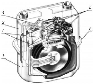
Fig. 8.10. Diaphragm counter: 1 - housing; 2 - cover; 3 - measuring mechanism; 4 - the crank-lever mechanism; 5 - the top valves of the gas distributing device; 6 - tightening strip
The diaphragm meter (Figure 8.10 ) consists of a housing 1, a cover 2, a measuring mechanism 3, a crank mechanism 4 connecting the moving parts of the diaphragms (membranes) to the upper valves 5 of the gas distribution device, valve seats (bottom of the switchgear) and a counting mechanism . The housing and the counter cover can be:
- - steel, stamped with a coating against corrosion and sparking. The connection between the steel stamped body and the cover is carried out by means of a sealing material and a tightening strip 6 (see Figure 8.10 ), which ensure a close fit of the two parts to each other;
- - Aluminum, cast. The housing and the meter cover in aluminum version are hermetically sealed with special gaskets and a set of screws, one of the screws is made with a seal.
Details and components of the measuring mechanism for membrane counters are made of plastics. The use of plastic measuring devices significantly reduces the cost of production, increases the resistance to chemical agents in gases, significantly reduces the coefficient of friction in the moving parts of the meter.
Depending on the design and volume of the gas being measured, the measuring mechanism can consist of two or four chambers. A schematic diagram of the operation of the diaphragm counter is shown in Fig. 8.11 .
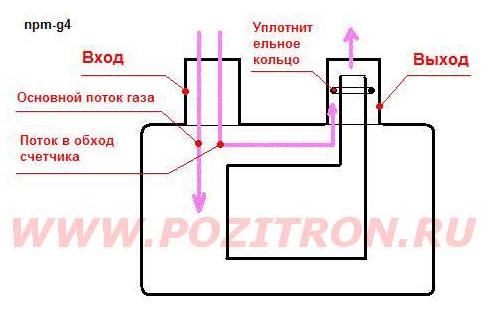
Fig. 8.11 . Schematic diagram of the operation of the diaphragm counter.
| Position of the counter chambers | Camera 1 | Camera 2 | Camera 3 | Camera 4 |
|---|---|---|---|---|
| a | Devastated | Filled up | Empty | Filled with |
| B | Empty | Filled with | Filled up | Devastated |
| at | Filled up | Devastated | Filled with | Empty |
| D | Filled with | Empty | Devastated | Filled up |
The counter works as follows:
A) the measured gas flow through the inlet pipe enters the upper cavity of the casing and then through the open valve into the chamber 2. The increase in the volume of gas in the chamber 2 causes the diaphragm to move and expel the gas from the chamber 1 to the outlet of the valve seat slit and then into the outlet of the counter. After the diaphragm lever approaches the wall of the chamber 1, the diaphragm stops as a result of switching the valve groups. The movable part of the valve of the chambers 1 and 2 completely overlaps the valve seats of these chambers, disconnecting this chamber unit.
B) The valve of the chambers 3 and 4 opens the gas inlet from the upper cavity of the meter body to the chamber 3, fills it, which causes the diaphragm to move and expel the gas from the chamber 4 into the outlet pipe through the slots in the valve seat. After the diaphragm lever approaches the wall of chamber 4, the diaphragm stops as a result of switching off the valve block of chambers 3, 4.
C) The valve of the chambers 1, 2 opens the gas inlet from the upper cavity of the meter body to the chamber 1. When the gas is supplied to the chamber 1, the diaphragm 1, 2 moves, displacing the gas from the chamber 2 into the output pair through the slots in the valve seat. After the diaphragm lever approaches the wall of chamber 2, the diaphragm stops as a result of switching off the valve block of chambers 1, 2.
D) The valve of the chambers 3, 4 opens the gas inlet from the upper cavity of the meter body to the chamber 4. When the gas is introduced into the chamber 4, the diaphragm 3, 4 moves and expels the gas from the chamber 3 into the outlet pipe through the slots in the valve seat. After the diaphragm lever approaches the wall of chamber 3, the diaphragm stops as a result of switching off the valve block 3, 4.
The process is repeated periodically. The counting mechanism counts the number of strokes of the diaphragms (or the number of cycles of operation of the measuring mechanism n). For each cycle, the volume of gas Vt is equal to the sum of the volumes of chambers 1, 2, 3, 4. One complete revolution of the output axis of the measuring mechanism corresponds to 16 cycles.
Braking method:
It is necessary to remove the counter from the gas pipeline (here not everyone can restore the seals on the union nuts) !!!!!!
The essence of the methods up to offensive is simple - inside the outlet branch pipe it is necessary to break the tightness of the connection between the plastic insert and the meter body. I just flexed the plastic slightly with a screwdriver and pinched the sealing rubber ring with tweezers and removed its result, exceeded all expectations, the counter twists less.
I understand that meters of this type are very sensitive to the pressure drop of gas inlet / outlet after this procedure, you can put a part of the sealer in place, and then I did not turn the poor guy when turning on the gas stove ....
I started counting only when the gas boiler was on. That's it. After this, put the meter on its place and restore the seals.
Sergey Frolov.
Turbine gas meters
In the turbine gas meter (Figure 8.13 ), under the influence of the gas flow, the turbine wheel is driven into rotation, the number of revolutions of which is directly proportional to the flowing volume of the gas. The speed of the turbine through the reduction gear and gas tight magnetic coupling is transferred to the counting mechanism located outside the gas cavity, showing (incrementally) the total volume of gas under operating conditions that has passed through the device.
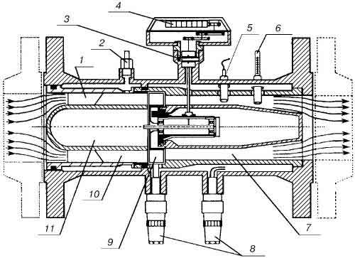
Fig. 8.13. Scheme of the gas turbine gas meter SP
1, 10 - measured cross-section; 2 - inclusion of pressure; 3 - magnetic coupling; 4 - counting mechanism; 5 - thermo-measuring probe RT-100; 6 - control thermometer; 7 - the output channel; 8 - impulse sensors; 9 - a wheel of the turbine; 11 - displacing the body.
The last gear wheel of the reducer is fixed with a permanent magnet, and near the wheel there are two reed switches, the frequency of closing the contacts of the first is proportional to the rotor speed of the turbine, i.e., the gas flow rate. When a powerful external magnetic field appears, the contacts of the second reed switch are closed, which is used to signal the unauthorized interference.
Structurally, turbine meters produced in Russia are a segment of a pipe with flanges, in the flowing part of which an inlet stream rectifier, a turbine unit with a shaft and bearing bearings and a rear support are arranged in series. On the body of the meter there is a plunger oil pump unit, through which a liquid oil is fed through the tubes to the bearing zone. On the body of the turbine there are places for installation of sensors of the equipment (for measuring pressure, temperature, pulses).
By the degree of automation of measurement and processing of measurement results, turbine meters are available in the following configuration options:
- - for separate measurements of variables of monitored parameters with randomly selected means for processing measurement results (manually operated counters, microcalculators, etc.);
- - for semi-automatic measurements of variable controlled parameters with computing devices for processing measurement results and devices with manual input of values of conditionally constant parameters or manual correction of measurement and calculation results;
- - for automatic measurements of all monitored parameters with computing devices for processing measurement results.
Rotary gas meters
In connection with the increase in the types of equipment, there was a need for measuring instruments that would have a relatively large throughput and a significant range of measurements with relatively small overall dimensions. These conditions are met by rotary gas meters, which additionally have the following advantages: no need for electricity, durability, the ability to monitor the serviceability of the pressure drop on the meter during operation, insensitivity to short-term overloads. Rotary counters are widely used in municipal services, especially in heating boilers, as well as in small and medium-sized enterprises.
Rotary (rotary) counter is a chamber gas meter in which eight-shaped rotors are used as the converter element.
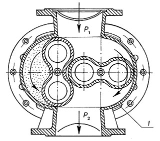
Fig. 8.12 Rotary gas meter type RG
11 - housing; 2 - rotor.
The rotary gas meter of the RG type consists of a casing 1 inside which two identical eight-shaped rotors 2 of the transfer and counting mechanisms rotate, connected to one of the rotors. The rotors are rotated by the difference in pressure of the gas flowing through the upper inlet and exiting through the lower outlet pipe. When rotating, the rotors roll over their lateral surfaces. Synchronization of rotation of the rotors is achieved by using two pairs of identical gears, fixed at both ends of the rotors in the end boxes outside the measuring chamber-housing. To reduce friction and wear, the gears of the rotors are permanently lubricated with oil poured into the end boxes.
The volume of gas displaced by half a revolution of one rotor is equal to the volume limited by the inner surface of the body and the lateral surface of the rotor occupying an upright position. For the full rotation of the rotors, four such volumes are displaced.
When manufacturing rotary counters, special attention is paid to the ease of rotation of the rotors and the reduction of unrecorded gas leaks through the meter. The lightness of the stroke, which is a qualitative indicator of the small friction in the mechanism and, consequently, of the small loss of pressure in the counter, is ensured by fitting the rotor shafts to the ball bearings, minimizing friction in the reducer and the counting mechanism, and also by rational choice of the design dimensions and rotor speed. Reduction of gas leaks is achieved by careful processing and mutual adjustment of the inner surface of the body and the friction surfaces of the rotors. The gap between the body and rectangular areas located at the ends of the largest diameters of the rotors varies from 0.04 to 0.1 mm, depending on the type of the counter. When manufacturing meters, special attention is paid to static balancing and processing of rotors.
Vortex flowmeters
Vortexes are flowmeters based on the dependence of the frequency of pressure oscillations arising in the flow in the process of vortex formation or oscillation of the jet either after an obstacle of a certain form established in the pipeline or a special twisting of the flow.
Vortex flowmeters have received their name from the phenomenon of vortex shedding that occur when an obstacle flows around a fluid or gas stream, usually in the form of a truncated trapezoidal prism (Figure 8.9 ). Behind the flow body is a sensing element that senses vortex oscillations
The merits of vortex flowmeters include: the absence of moving parts, the independence of readings from pressure and temperature, a large measuring range, a frequency measuring signal at the output, the possibility of obtaining universal calibration, a relatively low cost, etc.
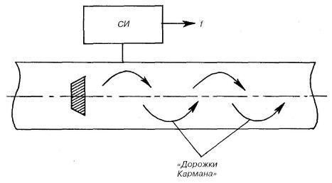
Fig. 8.9 Scheme of the vortex primary flow converter (SI - pulse counting device).
The drawbacks of vortex flowmeters include significant pressure losses (up to 30-50 kPa), limitations of their application: they are not suitable for low flow rates of the medium, for measuring the flow of contaminated and aggressive media.
Acoustic (ultrasonic) flowmeters
Acoustics are called flowmeters based on the measurement of a particular effect that occurs when oscillations pass through a flow of liquid or gas and depending on the flow. Almost all acoustical flowmeters used in practice operate in the ultrasonic frequency range and are therefore called ultrasonic.
Most industrial ultrasonic flowmeters use effects based on the movement of acoustic vibrations by a moving medium. They serve to measure volumetric flow, because the effects arising from the passage of acoustic vibrations through the flow of a medium (liquid or gas) are related to the velocity of the medium. In Fig. 8.8 shows the primary transducers of ultrasonic flowmeters.
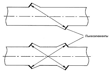
Fig. 8.8 Scheme of the ultrasonic primary flow transducer.
To introduce acoustic oscillations into the flow and to receive them at the outlet from the stream, radiators and oscillation receivers are needed - the main elements of the primary transducers of ultrasonic flowmeters. When compressing and stretching in certain directions of some crystals (piezoelements), electric charges are formed on their surface, and vice versa, if a potential difference is applied to these surfaces, the piezoelectric element will be stretched or compressed depending on which of the surfaces is more stressed - Piezoelectric effect. These effects are based on the method of transforming the variable electrical potential difference on the crystal faces into acoustic (mechanical) oscillations of the same frequency (for radiation of oscillations) or vice versa - the transformation of acoustic oscillations into an alternating electric potential difference on the crystal faces (for the oscillation receiver).
Advantages of ultrasonic flowmeters are a wide range of flow measurement and the possibility of using microprocessor technology. The main disadvantage of ultrasonic flowmeters is the sensitivity to the content of solid and gaseous inclusions.


Comments
Commenting on, remember that the content and tone of your message can hurt the feelings of real people, show respect and tolerance to your interlocutors even if you do not share their opinion, your behavior in the conditions of freedom of expression and anonymity provided by the Internet, changes Not only virtual, but also the real world. All comments are hidden from the index, spam is controlled.